Arduino CAN Bus Module 1st Network Tutorial
An Arduino Based CAN Bus Network
CAN (Controller Area Network) bus networks are found everywhere. They are found in vehicles, farm equipment, and in industrial environments. These networks allow for control and data acquisition. Depending on the application, they can be formed around a stringent set of standards (such as J1939) or in a ‘get it done’ approach suitable for an Arduino DIY project.
This tutorial introduces you to some very basic CAN bus principles and guides to building your first CAN bus network using the readily available Arduino CAN bus modules.
Required Material for the Tutorial
You’re going to need two Arduino’s for this tutorial. You’re also going to need to 2 Arduino CAN Bus Modules. These can be purchased at any of the sites below:
The Arduino CAN Bus Module pin outs and schematics can be found HERE.
Brief CAN Intro
In this description, I’m going to use the wordk ‘general’ a lot. There is a reason for that. CAN is a very flexible means of communications and has been adapted and defined to meet MANY standards. What is a firm rule for one may not be for another. What’s important here is that you get enough of an understanding to use CAN in your DIY project.
The image below is thus explained in very general terms.
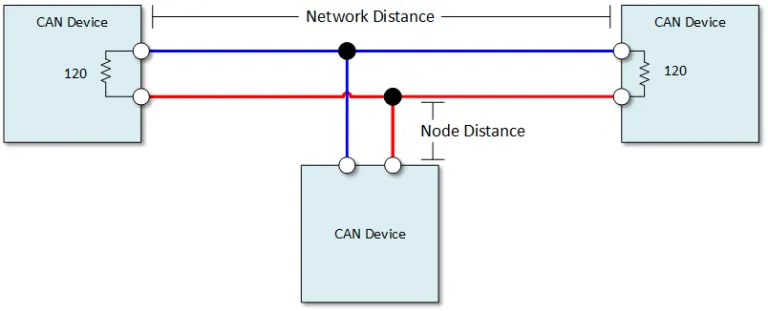
CAN Wires
There are two CAN wires. They are called CAN High and CAN Low. In applications that are designed to be robust, the wires are normally shielded twisted pairs. The shield is normally landed (or grounded) as one end.
CAN Speed and Distance
Communication speeds generally range from 50kpbs to 1Mbps. This maximum distance is drive by the selected speed. It can range from 40 meters at 1Mbps and 1000 meters at 50kpbs.
The general rule of thumb is that the shorter and slower the bus is, the more robust the communications.
Node distance is generally specified to be no more than 0.3 meters ( 1 foot).
The CAN Message
With CAN, we send and respond to messages over the CAN bus. A message contains an identifier and data.
The identifier is also known as a CAN ID or is sometimes to referred to as a PGN. The length of the identifier is either 11 or 29 bits in length.
The data can be anywhere from 0 to 8 bytes in length.
CAN Termination
A single 120 ohm resistor is generally used at the two ends of the CAN network. Nodes that hang of of the network can be up to 0.3 meters (1 foot) in length.
Arduino CAN Network Tutorial
This tutorial is very simple. Using our CAN transmitter we will create a CAN message and repetitively broadcast it. We will receive this CAN message using our CAN receiver. We will then display the received output in our serial monitor.
We will create messages from Arduino input and respond to those messages in future tutorials.
Get the Required Library
You are going to need the mcp_can.h library in order to run this tutorial. You can find that library HERE.
If you’re not familiar with installing libraries, you can read about it HERE.
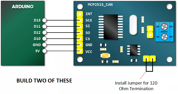
Build Arduino CAN Transmitter and Receiver
The receiver and transmitter are wired identically. Build two of these.
Copy, Paste and Upload the CAN Bus Module Receive Sketch
Upload the following sketch to one of your Arduinos. This will be the receiver.
// Henry's Bench
// 1st CAN Network - CAN RECEIVE

#include <SPI.h>
#include "mcp_can.h" // Library from https://github.com/Seeed-Studio/CAN_BUS_Shield


long unsigned int rxId;
unsigned long rcvTime;
unsigned char len = 0;
unsigned char buf[8];


const int SPI_CS_PIN = 10;


MCP_CAN CAN(SPI_CS_PIN);                                    // Set CS pin

void setup()
{
    Serial.begin(115200);


    while (CAN_OK != CAN.begin(CAN_250KBPS))            // init can bus : baudrate = 250K
    {
        Serial.println("CAN BUS Module Failed to Initialized");
        Serial.println("Retrying....");
        delay(200);
    }
    Serial.println("CAN BUS Module Initialized!");
    Serial.println("Time\t\tPGN\t\tByte0\tByte1\tByte2\tByte3\tByte4\tByte5\tByte6\tByte7");
}


void loop()
{

    if(CAN_MSGAVAIL == CAN.checkReceive())          // check if data coming
    {
        rcvTime = millis();
        CAN.readMsgBuf(&len, buf);    // read data,  len: data length, buf: data buf

        rxId = CAN.getCanId();

        Serial.print(rcvTime);
        Serial.print("\t\t");
        Serial.print("0x");
        Serial.print(rxId, HEX);
        Serial.print("\t");

        for(int i = 0; i<len; i++)    // print the data
        {
            if(buf[i] > 15){
              Serial.print("0x");
              Serial.print(buf[i], HEX);
            }
           else{
              Serial.print("0x0");
              Serial.print(buf[i], HEX);
           }

            Serial.print("\t");
        }
        Serial.println();
    }
}
Copy, Paste and Upload the CAN Bus Module Transmit Sketch
Upload the following sketch to your *other* Arduino. This will be the transmitter.
// Henry's Bench
// 1st CAN Network - CAN TRANSMIT

#include <mcp_can.h>
#include <SPI.h>


const int SPI_CS_PIN = 10;

// Build an ID or PGN
// This format is typical of a 29 bit identifier.. the most significant digit is never greater than one.
long unsigned int txID = 0x1881ABBA;
unsigned char stmp[8] = {0x0E, 0x00, 0xFF, 0x22, 0xE9, 0xFA, 0xDD, 0x51};

//Construct a MCP_CAN Object and set Chip Select to 10.
MCP_CAN CAN(SPI_CS_PIN);


void setup()
{
    Serial.begin(115200);

    while (CAN_OK != CAN.begin(CAN_250KBPS))              // init can bus : baudrate = 250K
    {
           Serial.println("CAN BUS Module Failed to Initialized");
           Serial.println("Retrying....");
           delay(200);

    }
    Serial.println("CAN BUS Shield init ok!");
}


void loop()
{
    // Serial.println("In loop"); // Optional: Uncomment for debugging

    // send the data:  id = txID, Extended Frame = 1, data len = 8, stmp: data buf

    CAN.sendMsgBuf(txID, 1, 8, stmp);
    delay(25);                       // send data every 25mS
}
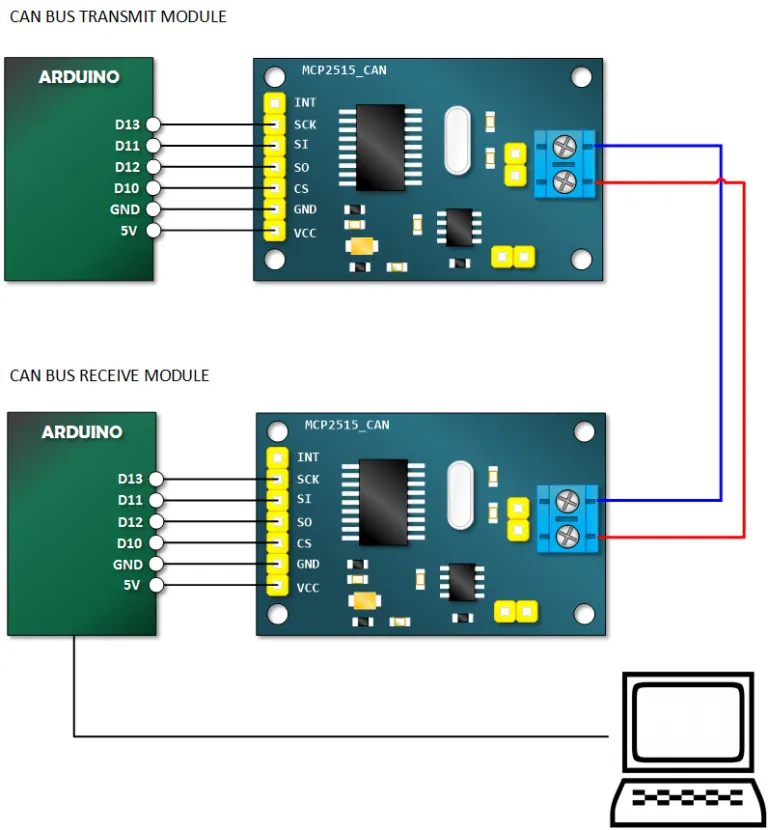
Connect the Transmitter and Receiver into a Network
You will need to power the transmitter with its own power source. The receiver will connect to your computer and will receive its power via USB.
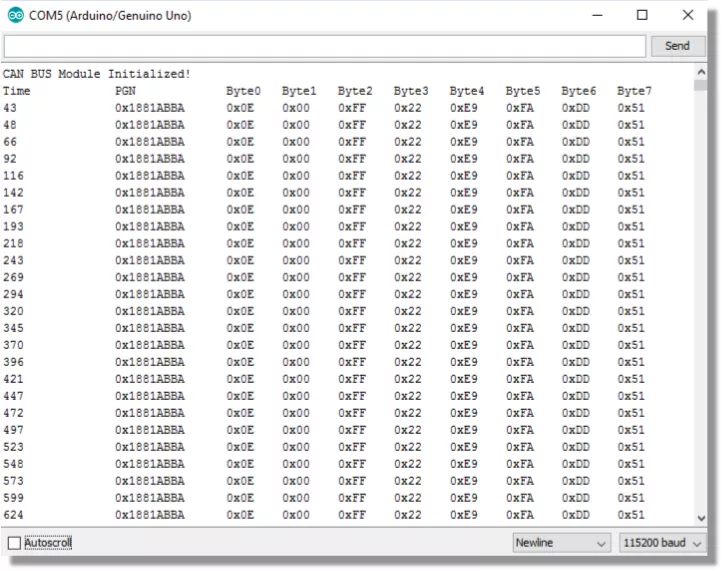
Open Serial Monitor and Verify Receiving of Data
With the receiver Arduino connected to your computer via USB, open the Arduino IDE Serial Monitor (ensure the baud rate is set to 115200). You should see output similar to the below, showing the received CAN messages: