Arduino Programmable Constant Current Power Supply
Arduino Controlled Constant Current Source
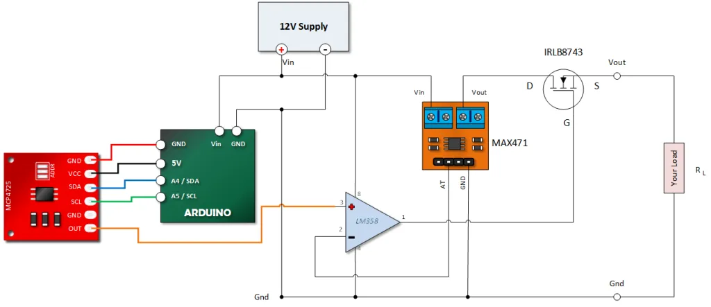
![]() This experimental project uses an MCP4725 Digital to Analog Converter, an LM358 Op Amp, an MAX471 Current Sensor and a logic level N-Channel Mosfet to create a constant current source.
This experimental project uses an MCP4725 Digital to Analog Converter, an LM358 Op Amp, an MAX471 Current Sensor and a logic level N-Channel Mosfet to create a constant current source.
We’re going to use the op amp in a non-inverting application. If you’re not all that familiar with op amps, you can read this Op Amp Basics Tutorial.
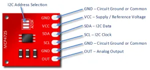
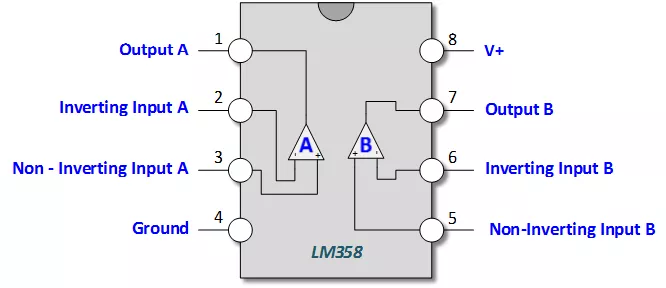
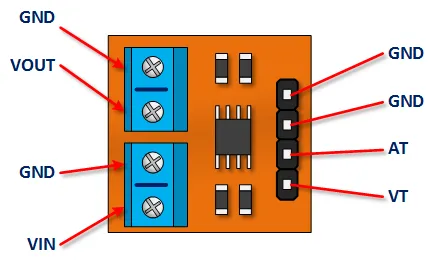
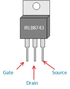
Component Pin Outs
Click on the images to get a better view.
MCP4725 Pin Outs
LM358 Pin Outs
MAX471 Pin Outs
IRLB8743 Mosfet Pin Outs
This is the Mosfet I used. Most logic level N Channel mosfets rated for the current will probably work.
Constant Current Source Function Description
Refer to the picture below:
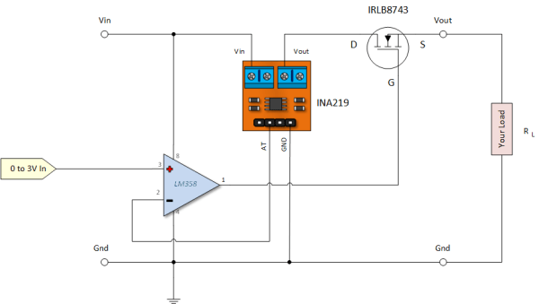
Fundamentally, we will use an LM358 to control the bias on the Mosfet until the current measured by the MAX471 matches what has been called for at pin 3 of the op amp.
The MAX471 has a very convenient output for this application is that it will provide a 1 volt output for 1 Amp of current measured. Its measurement range is limited to three amps, thus this constant current supply is limited to 3 amps.
It is important to keep this measurement range in mind as providing an input greater than 3 volts into the op amp could be a bit of a problem.
Arduino Programmable Constant Current Power Supply Tutorial
In this tutorial, we’re going to use an MCP4725 Digital to Analog Converter to provide an input to pin three of our op amp. You could also use an analog output from your Arduino directly as show in this example for a power supply.
Get the MCP4725 Library
Adafruit has created a library for this device that can be found HERE.
If you don’t know how to install libraries, you can read THIS ARTICLE.
Build Your MCP4725 Circuit
Your Mosfet is going to get hot. Put a heat sink on it.
Click on the image to enlarge.
My load was three 1 ohm 5W resistors in parallel.
Copy Paste and Upload the Code
#include <Wire.h>
#include <Adafruit_MCP4725.h>

Adafruit_MCP4725 dac; // constructor

void setup(void) {

  dac.begin(0x60); // The I2C Address: Run the I2C Scanner if you're not sure

}

void loop(void) {

    uint32_t dac_value;

    // Ask for 0.5A (MAX471 outputs 0.5V -> DAC input needs 0.5V)
    // 0.5V / 5V * 4095 = 409.5 -> use 410
    dac.setVoltage(410, false);
    delay(2000);

    // Ask for about 1A (MAX471 outputs 1V -> DAC input needs 1V)
    // 1V / 5V * 4095 = 819
    dac.setVoltage(819, false);
    delay(2000);

    // Ask for about 2A (MAX471 outputs 2V -> DAC input needs 2V)
    // 2V / 5V * 4095 = 1638
    dac.setVoltage(1638, false);
    delay(2000);

    // Ask for about 3A (MAX471 outputs 3V -> DAC input needs 3V)
    // 3V / 5V * 4095 = 2457
    dac.setVoltage(2457, false);
    delay(1000);


}
Test Your Circuit
There’s more than one way to do this. You can use your voltage meter to measure the voltage across the load or you can use your meter in the ammeter mode.