A Powerful Little Arduino Programmable 10V Supply
Contents
A Real Programmable Supply
In the Programmable 10VDC Signal Tutorial, I showed you how to create a programmable 10V DC signal source using an Arduino. The problem with that 10 volt source is that it was very limited by the LM358 in the current it could supply.
This tutorial takes is step further and shows you how to use both an Op Amp and a component designed to handle power ( like a darlington transistor or a mosfet) to create Programmable Power Supply with some oomph.
Getting the Components
The MCP4725 can be found at any of the sites below:
eBay Amazon Bang Good Deal Extreme
The LM358 is also readily available:
eBay Amazon Bang Good IC Station
I use a TIP122. You could easily get by with something else.
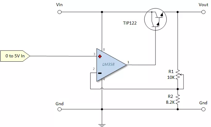
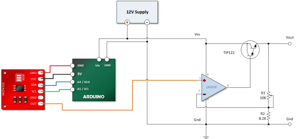
The Arduino Programmable 10V Regulated Supply Schematic
In this circuit we provide a 0 to 5 volt signal to the pin 3 of the LM358 Op Amp. The Op Amp then raises or lowers it’s output at pin 1 until the voltage at pin 2 matches the voltage being supplied to pin 3.
R1 in the circuit is adjusted to match R2.
Theory of Operation
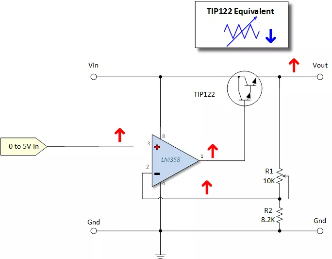
Increasing Voltage
Refer to the picture below. When the voltage into the Op Amp Pin 3 increases, the output at pin increases as. This raises the voltage at the base of the TIP122 and thus increases forward bias. The increase in forward bias raises the voltage at the voltage at Vout, thus increasing the voltage at Pin 2 via the voltage divider formed by R1 and R2.
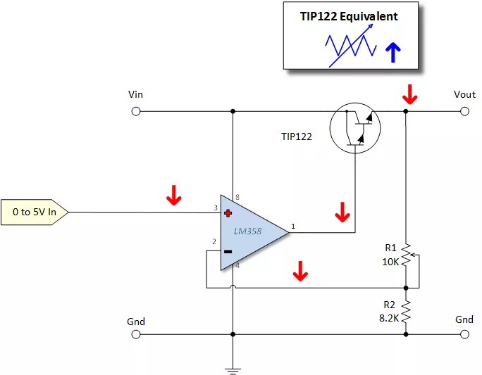
Decreasing Voltage
As illustrated below, a decrease at Pin 3, results in the exact opposite behavior. The output at pin 1 decreases, TIP122 has less forward bias and thus more resistance, Vout is therefore less and the voltage at pin 2 decreases.
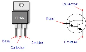
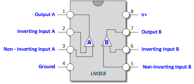
Key Component Pin Outs
The tutorial below makes use of the MCP4725, the TIP122 and the LM358. The diagrams below will help you identify the pins in the tutorial hook up.
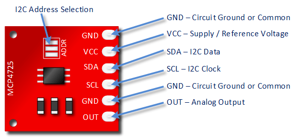
MCP4725 Pin Outs
We’ll be using the MCP4725 to generate the 0 to 5 Volt signal. You can find a tutorial on this device HERE.
If don’t have an MCP4725 and still want to try this tutorial, you can read the article on PWM to DC conversion found HERE. You’ll have to rework the code, but it should work.
Click the image below to enlarge and get a better view.
TIP122 Pin Outs
LM358 Pin Outs
The LM358 Op Amp is used in a non-inverting amplifier configuration. You can find an easy to read Op Amp Tutorial HERE.
Arduino Programmable Power Supply Tutorial
Download the Adafruit MCP4725 Library
The Adafruit library can be found HERE.
If you’re new to installing libraries, you can read THIS ARTICLE.
Connect Devices to Your Arduino
The TIP122 is rated for 5A of continuous current. I’m conservative in my projects, so I derate it to 3A. Even then, I use a heat sink.
Copy, Paste and Upload the Programmable Supply Demonstration Sketch
The sketch below increases the output by 2 volts in three second intervals and then restarts.
#include <Wire.h>
#include <Adafruit_MCP4725.h>

Adafruit_MCP4725 dac; // constructor

void setup(void) {

  dac.begin(0x60); // The I2C Address: Run the I2C Scanner if you're not sure

}

void loop(void) {

    uint32_t dac_value;

    // About 1V Out from MC4725
    // About 2V Out at TIP122 emitter
   dac.setVoltage(819, false);
    delay(3000);

    // About 2V Out from MC4725
    // About 4V Out at TIP122 emitter
   dac.setVoltage(1638, false);
    delay(3000);

    // About 3V Out from MC4725
    // About 6V Out at TIP122 emitter
   dac.setVoltage(2457, false);
    delay(3000);

    // About 4V Out from MC4725
    // About 8V Out at TIP122 emitter
   dac.setVoltage(3276, false);
    delay(3000);

    // About 5V Out from MC4725
    // About 10V Out at TIP122 emitter
   dac.setVoltage(4095, false);
    delay(3000);

}
Test Your Output
Connect a meter to the emitter of your TIP122 and ground. Your output should be growing in 2 volt increments and then restarting.