Arduino LM358 Op Amp PWM to Voltage Converter
Creating a DC Voltage using Your Arduino
The PWM output of your Arduino will work fine in many cases, particularly with motors and LEDs. However, what if you must have an actual DC voltage? This tutorial will show you how to create that analog voltage using an LM358 Op Amp.
You will need that Op Amp or one similar, along with a resistor and a capacitor.
Now, I’ve attempted to give you a functional description of the circuit, not only to aid you in understanding, but also so that you get a sense for how you may wish to tweak it.
That said, do feel free to jump right to the tutorial.
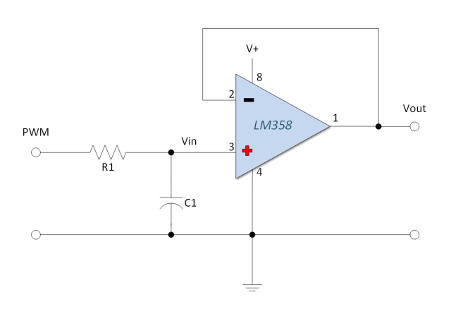
The LM358 Op Amp PWM to Voltage Converter
The circuit presented uses an LM358 Op Amp in a Non-Inverting Voltage Follower configuration. If you’re unfamiliar with Op Amps, you can read an easy to follow description HERE.
It also uses a resistor and capacitor in series to form an RC low-pass filter that smooths the PWM signal to the desired DC voltage.
You could omit the op amp, but it has some advantages. For one, it has a high input impedance (so it doesn't load the RC filter). Second, it offers a degree of protection for your Arduino and can buffer the output.
PWM to Voltage Converter Functional Description
The image and text below serve to give you a sense of how this circuit works.
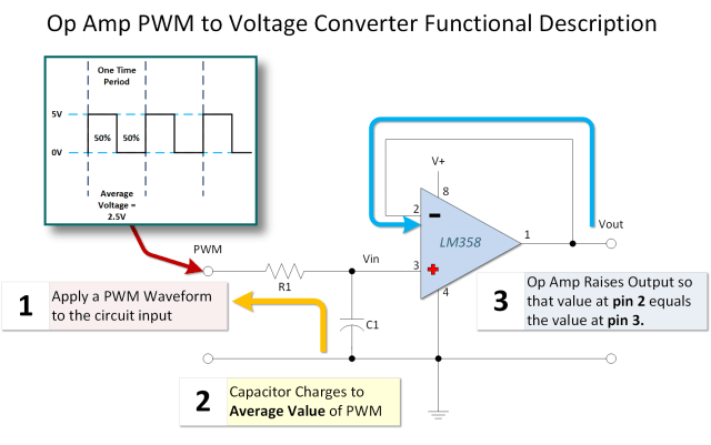
1) A PWM signal is applied to the input of the circuit. Pulse width modulation has few characteristics that are important to us.
- The first is the period of the signal (or its inverse, the frequency). That is to say, how frequently the PWM signal repeats itself.
- Next we’re interested in the amplitude, or how high the signal goes in volts (typically 0V to 5V for Arduino Uno).
- Finally, we want to know the percentage of time the signal is on (the duty cycle).
2) Next, the capacitor C1 charges through R1 towards the average value of the PWM signal. The time it takes to charge and discharge is determined by the RC time constant. The values for the capacitor and resistor are largely driven by the time period (frequency) of the PWM signal. Another consideration in resistor selection has to do with maximum current handling capability of the Arduino Output. The capacitor should also have a voltage rating higher than the maximum voltage it is expected to charge to (e.g., > 5V).
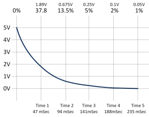
- One time constant (τ) in seconds = Value of Resistor in Ohms × Value of Capacitor in Farads.
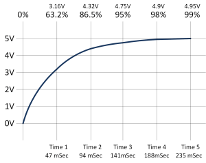
- It takes approximately five time constants (5τ) for the capacitor to charge (or discharge) to about 99.3% of the final value.
3) Finally the Op Amp (configured as a voltage follower) buffers the voltage across the capacitor. It adjusts its output so that the voltage at the output pin equals the voltage at its non-inverting input (pin 3), which is connected to the capacitor voltage.
Circuit Low Pass Filter in More Depth
C1 and R1 in our circuit form a low pass filter. That means it is designed to pass lower frequencies (like the DC average voltage) while blocking or attenuating higher frequencies (like the rapid switching of the PWM signal). It establishes a time constant that allows the capacitor voltage to settle near the average DC value of the Arduino PWM output.
The PWM to Analog Converter Charge Time Constant
I’ve selected 4700 ohms for R1 and a 10uF cap for C1. I did it because it will work and (more importantly) because its what I have around.
Thus my time constant (τ) is 4700 Ω × 0.000010 F = 0.047 seconds (or 47 milliseconds).
When superimposed on a classical RC time constant curve (charging towards 5 volts), it will look something like this:
The PWM to Analog Converter Discharge Time Constant
To get a sense for how the low pass filter interacts with the PWM, it also useful to look at the discharge time constant. The curve is the inverse of the charge curve.
The PWM Signal Characteristics
There are two default PWM frequencies on the Arduino Uno. One is approximately 490 Hz (on pins 3, 9, 10, 11) and the other is approximately 980 Hz (on pins 5, 6). I’m using pin 3, which has a ~490 Hz frequency. The time it takes for it to complete one cycle (the period) is the inverse of the frequency:
Time in Seconds = 1 / Frequency in Hertz
Therefore the period is 1 / 490 ≈ 0.00204 seconds or 2.04 milliseconds (mSec).
If we select a 50% duty cycle (`analogWrite(pin, 128)`), the timing will look something like this:
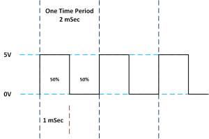
Notice how the output of the PWM falls low after about 1 mSec. At this point in time, the capacitor begins discharging.
How the the Low Pass Filter is Charged
So we have a capacitor that takes roughly 5 * 47 mSec = 235 mSec to fully charge, but the PWM signal is only HIGH for about 1 mSec at a 50% duty cycle. On the surface, you might conclude that it will never charge up. However, if you examine the charge and discharge cycles closer, you will see that it does charge (albeit slowly) in a pattern that looks like a warped stairway, eventually settling near the average voltage.
Start with the first charge cycle
In that first millisecond of HIGH time, the capacitor starts charging towards 5V. Using an RC time constant calculator (or the formula Vc = Vs * (1 - e^(-t/RC))), with Vs=5V, R=4700, C=10uF, t=0.001s, the capacitor charges to approximately 0.105V.
Examine the first discharge cycle
When the PWM signal goes LOW for the next 1 mSec, the capacitor starts discharging from 0.105V towards 0V. Using the discharge formula (Vc = Vo * e^(-t/RC)), it discharges only slightly, perhaps down to about 0.103V.
Second Charge Cycle
In the second charge cycle, the capacitor starts at ~0.103V and charges towards 5V for 1 mSec. It gains slightly more voltage than in the first cycle because the voltage difference driving the charge (5V - 0.103V) is still large. It might reach ~0.206V.
Second Discharge Cycle
During the next LOW phase, it discharges from ~0.206V, again dropping only slightly to maybe ~0.201V.
Completing the Low Pass Filter Charge
This 'step' process of charging slightly more than discharging continues over many cycles until the capacitor voltage stabilizes around the average value of the PWM signal (which is DutyCycle * VCC, e.g., 0.50 * 5V = 2.5V for a 50% duty cycle).
Once stabilized, the small charge and discharge cycles create a small ripple voltage around the DC average. The larger the RC time constant relative to the PWM period, the smaller the ripple. My setup yielded about 50 mV of ripple.
Arduino LM358 Op Amp PWM to Voltage Out Tutorial
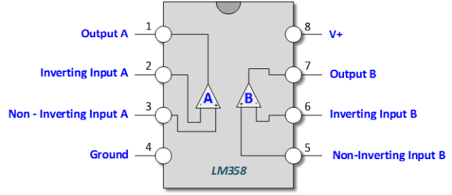
LM358 Pin Outs
If you use an 8-pin DIP package LM358, the pins are as shown below. Note that the LM358 contains two independent op-amps; we are only using one (pins 1, 2, 3) in this circuit.
Connect Your LM358 Circuit to Your Arduino
Wire the circuit as shown in the schematic. You will need an external power supply for the LM358 (Pin 8 and Pin 4) that is higher than the maximum desired output voltage (e.g., 9V or 12V works well if you want a full 0-5V output range). **Do not power the LM358 directly from the Arduino 5V pin if using a supply greater than 5V.** Ensure the ground of the external supply is connected to the Arduino's ground.
If you power the Op Amp with only 5 Volts, the output voltage (Vout) will typically be limited to about 1-1.5V less than the supply rail (around 3.5V-4.0V max).
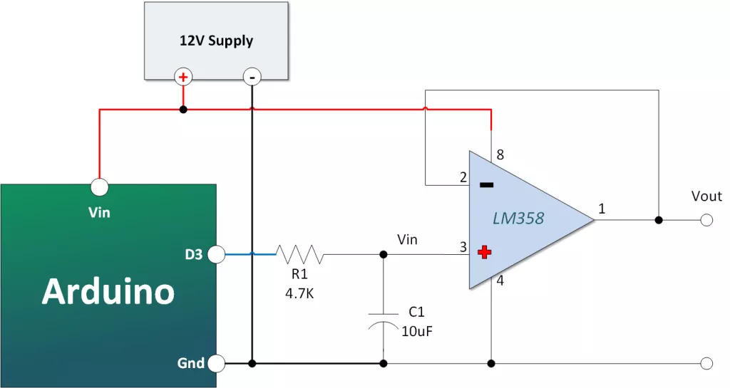
- Arduino PWM Pin 3 to R1 (4.7kΩ)
- Other end of R1 connects to C1 (10uF) positive lead AND LM358 Pin 3 (Non-inverting input)
- C1 negative lead to GND
- LM358 Pin 2 (Inverting input) connects to LM358 Pin 1 (Output)
- LM358 Pin 8 connects to External Power Supply Positive (+) (e.g., +9V)
- LM358 Pin 4 connects to GND (connect to Arduino GND and External Supply GND)
- LM358 Pin 1 (Output) is your DC voltage output. You can connect a voltmeter here or connect it to Arduino Analog Pin A0 to measure it.
Copy, Paste and Upload the Arduino PWM to Voltage Out Converter Sketch
The sketch cycles through various PWM duty cycles (`analogWrite` values from 0 to 255) in 3-second intervals, allowing you to observe the corresponding DC voltage output.
// Emre's Bench - LM358 Arduino PWM to Voltage Converter

const int pwmOutPin = 3;  // Arduino PWM output pin (~ on Uno/Nano)
// const int voltageReadPin = A0; // Optional: Connect Vout to A0 to read back

void setup() {
  pinMode(pwmOutPin, OUTPUT);
  // Serial.begin(9600); // Optional: for debugging
  // Serial.println("PWM to DC Voltage Converter Test");
}

void loop() {
  // float measuredVoltage; // Optional
  // int adcReading; // Optional

  // Serial.print("Setting PWM: 0 -> "); // Optional
  analogWrite(pwmOutPin, 0); // Output ~0 volts
  delay(3000);
  // adcReading = analogRead(voltageReadPin); measuredVoltage = (adcReading * 5.0) / 1023.0; Serial.println(measuredVoltage); // Optional

  // Serial.print("Setting PWM: 51 -> "); // Optional
  analogWrite(pwmOutPin, 51); // Output ~1 volt (51/255 * 5V)
  delay(3000);
  // adcReading = analogRead(voltageReadPin); measuredVoltage = (adcReading * 5.0) / 1023.0; Serial.println(measuredVoltage); // Optional

  // Serial.print("Setting PWM: 102 -> "); // Optional
  analogWrite(pwmOutPin, 102); // Output ~2 volts (102/255 * 5V)
  delay(3000);
  // adcReading = analogRead(voltageReadPin); measuredVoltage = (adcReading * 5.0) / 1023.0; Serial.println(measuredVoltage); // Optional

  // Serial.print("Setting PWM: 128 -> "); // Optional
  analogWrite(pwmOutPin, 128); // Output ~2.5 volts (128/255 * 5V)
  delay(3000);
  // adcReading = analogRead(voltageReadPin); measuredVoltage = (adcReading * 5.0) / 1023.0; Serial.println(measuredVoltage); // Optional

  // Serial.print("Setting PWM: 153 -> "); // Optional
  analogWrite(pwmOutPin, 153); // Output ~3.0 volts (153/255 * 5V)
  delay(3000);
  // adcReading = analogRead(voltageReadPin); measuredVoltage = (adcReading * 5.0) / 1023.0; Serial.println(measuredVoltage); // Optional

  // Serial.print("Setting PWM: 204 -> "); // Optional
  analogWrite(pwmOutPin, 204); // Output ~4.0 volts (204/255 * 5V)
  delay(3000);
  // adcReading = analogRead(voltageReadPin); measuredVoltage = (adcReading * 5.0) / 1023.0; Serial.println(measuredVoltage); // Optional

  // Serial.print("Setting PWM: 255 -> "); // Optional
  analogWrite(pwmOutPin, 255);  // Output ~5.0 volts (255/255 * 5V)
  delay(3000);
  // adcReading = analogRead(voltageReadPin); measuredVoltage = (adcReading * 5.0) / 1023.0; Serial.println(measuredVoltage); // Optional
}
Test Your Output
Connect a voltmeter between the op-amp output (Pin 1) and ground. After uploading the sketch, you should observe the voltage stepping up approximately every 3 seconds, corresponding roughly to the target voltages (0V, 1V, 2V, 2.5V, 3V, 4V, 5V), assuming a 5V Arduino PWM amplitude and adequate op-amp power supply.