Op Amp Basics for Arduino Hobbyists
Who Is This Written For?
I have struggled with the idea of writing this Op Amp article. Indeed, I’ve started and stopped at least a dozen times.
You see, there’s already a bunch of excellent information (which you may ultimately want to read) offered by people who are far more knowledgeable about this component than I.
However, most of those articles are directed at those of us who first learned about things like Common Mode Rejection and Thevenin’s Theorem in classrooms.
Therein lies the problem.
Arduino enthusiasts come from different backgrounds. Some of us are hardcore hardware hacks, some are code geeks, some are gear heads and some are artistic. Better yet, some of us are an eclectic blend of everything with expertise in nothing.
While there are those classical purists who insist that learning about electricity and magnetism begin with a discussion of the make up of atoms, I’m not one of them. I think there are many paths to learning and ultimately to solving problems. Therefore, my approach is a tad different. That isn’t to say that you should never learn about valence electrons. You may wish to one day.
Instead, I don’t think that B necessarily has to follow A.
This is for the Arduino aficionado who isn’t classically educated. Its for the person who tinkers first and studies second.
What this article sets out to do, is to make the reader aware that there is a really cool component called an Op Amp, to very basically discuss how it functions, and to show some of its commonly used configurations within circuits.
How you use this electronic Lego to complete your micro-controller masterpiece is entirely up to you. In future articles, I will introduce some Arduino examples that make use on an Op Amp.
Very Basic Op Amp Functionality
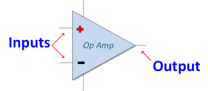
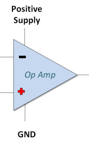
Two Inputs and One Output
Simply put…
- It accepts two inputs.
- It provides a single output
What the Output Does
The output responds to an input by raising or lowering its voltage until the voltage at the inputs are equal.
This is done by connecting the op amp in such a way that feedback is provided to one of the inputs. You’ll see some circuits with feedback a little further on.
In a sense, the device works to create a balance.
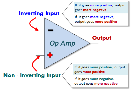
Inverting and Non-Inverting Inputs
The two inputs to the Op Amp each will affect the output differently. Their names derive from how they affect the output.
The input with minus sign (-) is known as the Inverting Input. When it increases (or goes more positive), the output decreases (or goes more negative). Conversely, if the inverting input goes more negative, the output will go more positive.
The input with the plus sign (+) is known as the Non-Inverting Input. It causes to output to behave exactly the opposite of the inverting input. If it goes more positive, the output will go more positive. If it goes more negative, the output will go more negative.
Op Amp circuits on the internet don’t always include a thorough functional explanation. For you to make use of these circuits, you will want to thoroughly grasp how these inputs affect the output.
Bi-Polar and Uni-Polar Op Amps
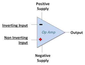
The op amp comes in a variety of packages that include DIP, Surface Mount, Cans and others. Regardless of the package, the Op Amp will have at least five pins (two inputs, one output, positive power, negative power/ground).
The inputs and outputs have been sufficiently discussed for now. That said, it is useful to discuss the pins used to provide power.
While the voltages we apply to those pins clearly depend on the op amp's specifications, it is important to know that there are a couple basic flavors available: Bi-Polar and Uni-Polar.
What you use will be application driven. While you can use both with an Arduino, I lean towards using the uni-polar variety in my circuits when I can as it is often simpler to power from a single Arduino supply.
Bi-Polar Op Amp
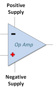
The Bi-Polar Op Amp is the style most commonly featured in various sample schematics found online. For power, it is designed to receive both a positive and a negative voltage supply (relative to a common ground).
It is extremely useful if you need to provide an output voltage that can swing both above and below zero volts (ground).
With some thought, it is possible to design a circuit that grounds the negative supply terminal (V- or Vss), effectively running it from a single positive supply. However, this might limit its output swing capabilities compared to using a true bipolar supply.
Uni-Polar Op Amp
The uni-polar (or single-supply) op amp is designed to operate with a single positive power supply input and a ground connection.
It’s my personal favorite when integrating into typical microcontroller applications where only a single positive voltage (like 5V or 3.3V) is readily available.
In future articles, you will see me discussing the LM358. That device is a unipolar op amp (though it can also be operated from bipolar supplies).
Common Op Amp Circuit Configurations
Here’s where we start getting to the cool stuff and reinforcing concepts we have already discussed.
Each of the circuits shown uses feedback. Remember, the op amp will work to raise or lower its output until both inputs are (ideally) equal.
The Op Amp Voltage Follower
The illustration below shows a voltage follower (also called a buffer). In this circuit, the output voltage ideally equals the input voltage (Vout = Vin).
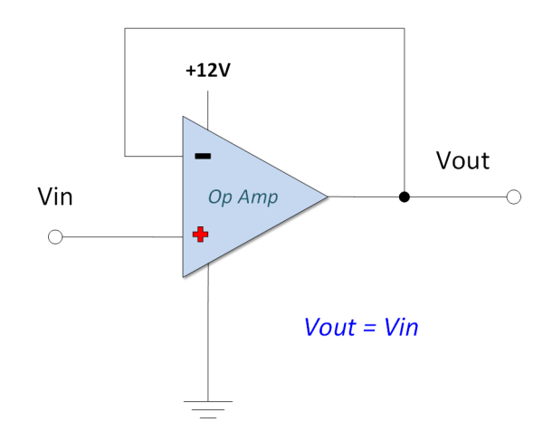
The primary benefit here is impedance buffering. The op amp's input impedance is extremely high, so it draws virtually no current from the input source (like a sensor or a weak Arduino output). The op amp's output, however, can typically source or sink more current than the original input source, allowing it to drive heavier loads without affecting the input signal.
Notice how the output is connected directly back to the inverting input. The op amp adjusts its output voltage until the inverting input voltage equals the voltage at the non-inverting input (Vin). Five volts in gets you five volts out (within the op amp's output swing limits).
The Op Amp Non-Inverting Amplifier
With the non-inverting amplifier, we introduce gain (Rf) and feedback (Rg) resistors. These resistors determine the amount of amplification (or gain) applied to the input signal.
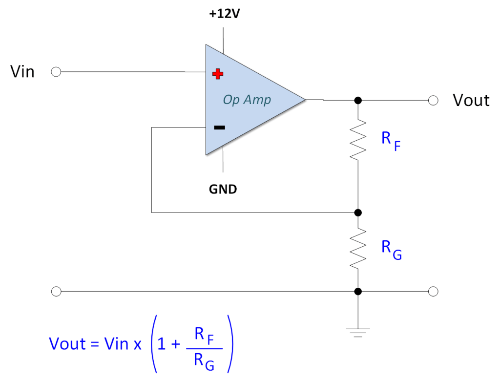
In this circuit, the output voltage is fed back to the inverting input through a voltage divider formed by Rf and Rg. The op amp adjusts its output (Vout) until the voltage at the inverting input (determined by the divider) equals the voltage applied to the non-inverting input (Vin).
The voltage gain (Av) for this configuration is given by the equation:
Vout = Vin * (1 + Rf / Rg) or Gain (Av) = 1 + (Rf / Rg)
Since the gain is always greater than 1, this circuit amplifies the input voltage without inverting its polarity.
The Op Amp Inverting Amplifier
As the name suggests, the inverting amplifier provides an output voltage that is an amplified, inverted version of the input voltage (a positive Vin results in a negative Vout relative to the reference, and vice-versa).
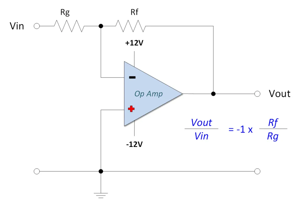
In this configuration, the input signal (Vin) is applied through the gain resistor (Rg) to the inverting input. The non-inverting input is typically connected to ground (or a reference voltage). The feedback resistor (Rf) connects the output back to the inverting input.
The op amp works to keep the voltage at the inverting input equal to the voltage at the non-inverting input (which is 0V or ground in this case). This point is often referred to as a "virtual ground".
The voltage gain (Av) for this configuration is determined by the ratio of the feedback resistor to the gain resistor:
Vout = -Vin * (Rf / Rg) or Gain (Av) = - (Rf / Rg)
The negative sign indicates the inversion of the output signal relative to the input.