Arduino MAX471 Power Meter Tutorial
Using the MAX471 B43 Module as a Power Meter
The MAX471 measures both current and voltage, thus making it ideal for a quick power measurement.
It is powered by the source to be measured. The maximum measurable current is three amps and the voltage measurement range is from 3 volts to 25 volts. This tutorial shows you how to make both these measurements and combine them into a power measurement.
Getting One
There are two flavors of this module available. The first module is configured for a current only measurement. It can be seen HERE.
This module is set up for both current and voltage. They can be found from the vendors listed below.
MAX471 Pin Outs
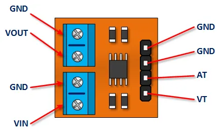
GND: All of the grounds are connected to the same electrical point
VOUT: Connects the high side of your load
VIN: Connects to the Positive Pole of your voltage source ( This can be anywhere from 3 to 25 Vdc )
AT: Provides 0 to 5V signal that is scaled to 1 V per amp.
VT: Provides a 0 to 5V signal that is scaled to 1 volt per for every 5 volts input
Arduino MAX471 Watt-meter Tutorial
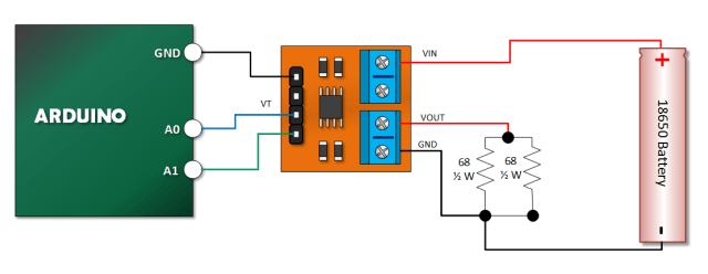
Connect Your Arduino to the MAX471, a Load and a Power Source
I’m using an 18650 battery, while the nominal voltage is 3.6 volts it can be as high as 4.0 volts when fully charged. I use that value to determine the load resistance for my test.
I find that if I put a 32 ohm resistor across the battery, I will draw about 0.124 amps and dissipated 0.5 watts through the resistor.
Since I had 1/2 Watt 68 0hm resistors, I put two in parallel to yield a nominal 34 ohms with the ability to safely dissipate 1 Watt of heat. So, I am above the 3V supply requirement, below the 3A current ceiling and have chosen a safe enough load for test purposes.
Copy, Paste and Upload the Power Meter Tutorial Sketch
Simple stuff. We read voltage, current and multiply them to get power. Remember, with voltage we’re going to multiply whatever value we read by five to yield the value measured by the MAX471.
// Emre's Bench
// MAX471 Power Meter Tutorial

#define VT_PIN A0
#define AT_PIN A1

void setup()
{
  Serial.begin(9600);
}

void loop()
{
  int vt_read = analogRead(VT_PIN);
  int at_read = analogRead(AT_PIN);

  // Voltage calculation: (ADC Reading / ADC Resolution) * Vref * Scaling Factor
  float voltage = vt_read * (5.0 / 1024.0) * 5.0; // 5V Vref, 10-bit ADC, 5:1 voltage scaling

  // Current calculation: (ADC Reading / ADC Resolution) * Vref / Current Scaling (1V/A)
  float current = at_read * (5.0 / 1024.0); // 5V Vref, 10-bit ADC, 1V/A scaling

  // Power calculation: P = V * I
  float watts = voltage * current;

  Serial.print("Volts: ");
  Serial.print(voltage, 3);
  Serial.print("\tAmps: ");
  Serial.print(current,3);
  Serial.print("\tWatts: ");
  Serial.println(watts,3);
  // Serial.println(); // Removed extra blank line for cleaner output

  delay(500);
}
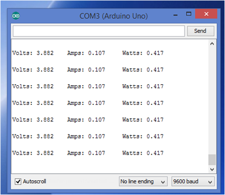
Verify Your Sketch Output
Open your serial monitor. If everything worked out, you receive will have an output that looks something like the picture below: