Arduino 18650 Battery Charger: Project 1
Your First Arduino 18650 Charger
This lithium battery is perhaps one of the most commonly used batteries today. It can be found in laptop computers, hand tools, electric cigarette’s and even electric vehicles. My personal experience has to do with being an engineer that designs the latter.
In this article, you will be introduced to some battery charging basics and you will be shown how to build a charger using an Arduino and some readily available parts. More, an experienced user should be able to substitute their own parts to accomplish the same thing.
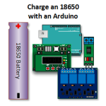
Arduino 18650 Charger Parts
About my Specifications
On some of the specifications you will note that I’m asking you to use parts that have specifications that are significantly greater than what is actually required. I do this because I’m not in the habit of proving that Chinese manufactured parts for hobbyists meet specifications.
In my experience, some do and some don’t. Since I really have no desire to prove that something does not work by burning down my house, I stay well away from device limits for continuous operation and MAYBE 80 percent of rated for short peaks.
A Constant Current Constant Voltage Power Supply
A key component to battery charging is the ability to regulate both current and voltage. The Minghe B3603 allows you to do just that. Depending on your charge rate, you should be able to provide at least 4.2 volts at 2.5 amps or better. I use significantly less current because I have an interest in maintaining what is known as cycle life.
A Relay or Relay Module
You will want relays that have at least a 5 amp contact rating. The commonly available Arduino 5V relay modules work just fine. I’m using a four channel module. A single or two channel module works too. This article discusses the four channel module. An automotive relay will also work.
A Current Sensor
I’m using an ACS712 5 amp sensor. An INA219 also works.
An 18650 Battery
I’m charging a Samsung ICR18650-26F. Use whatever you want. However in order to charge this cell safely, you’re going to need to know what the manufacturer specifies for a charging profile. You can get that information from datasheets or manufacturer web sites.
Those cells you see advertised at incredibly low prices with unbelievable specifications probably shouldn’t be trusted… never mind the charging profiles they specify in their ads.
About 18650 Two Stage Charging
While they may not say so explicitly, most 1865o manufacturers are going to specify two stage charging. What you will need to be able to do is read the manufacturer specifications and derive a two stage charging definition from those specifications.
These stages are as follows:
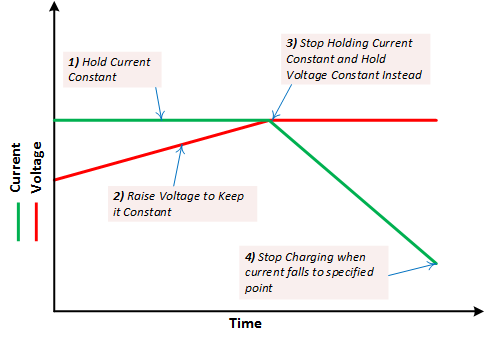
- Constant Current – Voltage Limited: In the lead acid world, this is also known as a bulk charge. In this mode, a constant current is supplied to the battery. As the battery becomes more charged, the amount of voltage necessary will maintain this current will increase. This stage of charging is considered complete when the voltage has increased to a specified value.
- Constant Voltage: In this mode, the voltage is held constant. As the battery approaches a full charge, the current will decrease. This current is monitored until the current falls to a specified level.
The image below graphically illustrates these modes.
Example of Deriving a Two State Charging Profile
In order to derive a charging profile for my Samsung 18650, I consulted the datasheet. Specifically, I referred to tables found in section 3 and section 7.
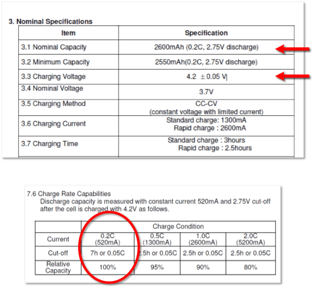
In table three, I found the Amp Hour (AH) capacity of the cell. It is specified for 2600 mAH. *The ‘0.2C’ and ‘2.75 volt‘ in the parenthesis next to this rating means that if you were to discharge this cell at rated equivalent to 1/5th of its rated capacity, you would deliver 2600 mAH by the time the voltage fell to 2.75 volts.*
Table three also gives me some specifications for the charge voltage. The charge needs to be brought to 4.2 volts, plus or minus 50 mV.
Table seven gives us the final pieces of the puzzle.
Notice that it give us more than one charge rate and notice how these charge rates affect overall capacity. For this project, I am selecting the charge rate that provides 100 percent of capacity or 520 mA.
More using table seven, I determine that I am going to cut off charging when the current falls to 130 mA (2600 * 0.05C). *Notice how it specifies 7h or 0.05C. What this means, is that you shut off charging for whichever condition occurs first. I’m not using the 7 hour limitation in this introductory project as I’m just trying a concept. If I were to make this a permanent installation, I would add this and a few other features that would make my charger more bullet proof.*
When put together, all of this information tells us how to charge this battery and thus what we will be building with my charger. This is what it looks like.
- Constant Current: The battery will be charged at 520 mA until the voltage reaches 4.2 volts
- Constant Voltage: When the battery reaches 4.2 volts, it will be held there while the current is monitored. When the current falls to 130 mA, charging will shut off.
Arduino 18650 Battery Charger Tutorial
Setting Up the CC-CV Power Supply
Constant Current – Constant Voltage (CC-CV) power supplies allow us to select to parameters for regulation and/or limiting. They allow us to:
- Select a Current set point
- Select a Voltage set point
When placed into operation, the power supply will:
- Try to raise the voltage while monitoring the current.
- If the current point is reached, the power supply will stop raising the voltage and hold the current. This is the constant current mode and is precisely what is required for the first charging stage.
- When the voltage set point is reached, the power supply will hold the voltage and let the current fall (or rise) as necessary to maintain the voltage. Keep in mind, that it will never let the current rise beyond the current limit.
If you’re using the Minghe B3603, you will want to set the voltage to 4.2 volts and the current to 0.520 A.
If you’re using another supply, you will need to refer to documentation that tells you how to establish these values.
Build Your Arduino 18650 Battery Charger
Refer to the schematic below and make your connections. I recommend turning your charger output off at this point.
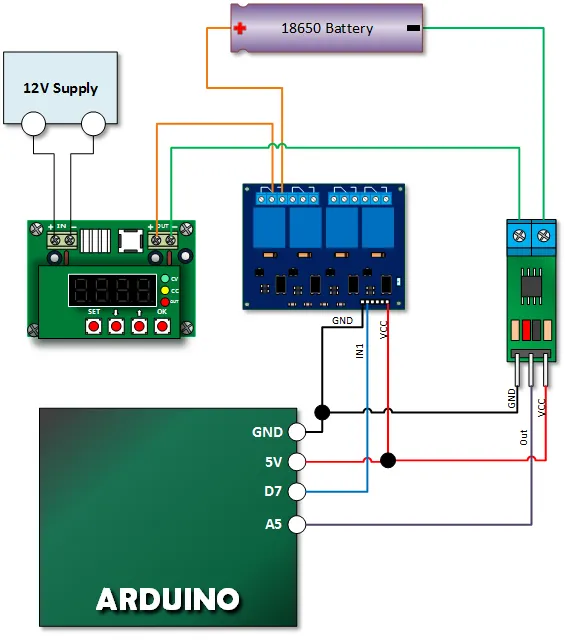
Copy Paste and Upload Your Lithium Charger Code
Upload your sketch. If you study the sketch, you will see that the current sensor is monitored to ensure that we shut off charging when current has fallen to 0.05 C. The power supply programming was done within the power supply itself.
// Emre's Bench
// Arduino 18650 Battery Charger - Project 1
// Based on original code by Henry's Bench

/*
Measuring Current Using ACS712
*/
const int analogIn = A5;
int nRelayDrive = 7;

int mVperAmp = 185; // use 100 for 20A Module and 66 for 30A Module - *** CALIBRATE THIS ***

int RawValue= 0;
// Calibrate this value by reading analogIn with no current flowing
int ACSoffset = 2500; // Should be Vcc/2 in mV (e.g. 2500 for 5V)
double Voltage = 0;
double Amps = 0;
boolean bCharged = false;

void setup(){
 Serial.begin(9600);
 pinMode(nRelayDrive,OUTPUT);
 digitalWrite(nRelayDrive, HIGH); // Initialize relay to OFF state (for active-low modules)
 Serial.println("BEGIN");
 }

void loop(){
  if(!bCharged){
    digitalWrite(nRelayDrive, LOW); // Turn relay ON (Active LOW)
    delay(2000);
    chargeBattery();
    digitalWrite(nRelayDrive, HIGH); // Turn relay OFF
  }
}

void chargeBattery(){
  do{
     // Read multiple times and average for stability
     long rawValueSum = 0;
     for (int i = 0; i < 10; i++){
         rawValueSum += analogRead(analogIn);
         delay(2);
     }
     RawValue = rawValueSum / 10;

     Voltage = (RawValue / 1023.0) * 5000.0; // Gets you mV (assuming 5V Arduino)
     Amps = ((Voltage - ACSoffset) / mVperAmp);

     Serial.print("Current = "); // shows the current measured
     Serial.println(Amps,3); // the '3' after amps allows you to display 3 digits after decimal point
     delay(1000);
  } while (Amps > 0.130); // Termination current (e.g., 130mA or 0.05C for 2600mAh cell) - ADJUST AS NEEDED

  bCharged = true;
  Serial.println("Battery is Charged");
}
Run the Program
Enable the output of your power supply and run your program. Open your serial monitor and see that current is held relatively constant until the voltage is reached. At that point, the power supply reaches a constant voltage mode and current begins to fall.
When it falls to the specified value, charging is stopped.
Opportunities for Improving this Project
- Twist and Shield your ACS712 wire to make it more stable
- Add a voltage reference to make the current measurement more accurate
- Use an LTC2400 to make the current measurement more accurate
- Measure the cell surface temperature to ensure that it never exceeds specifications
- Measure ambient temperature to make sure you do not charge when it is too cold.
- Improve cycle life by only charging to 90 percent
- Have and automatic cut out when charging has exceeded a time limit