Arduino 12V Automotive Relay Tutorial (Using a TIP122)
Using a 12V Automotive Relay with an Arduino
The outputs from an Arduino can be set to HIGH or LOW. Often, we can use these digital outputs to drive or signal various devices directly. However, there are limitations, specifically regarding current.
Arduino pins are typically limited to sourcing or sinking around 20 mA (absolute maximum is often 40mA, but sustained current should be much lower). Driving devices that require more current than this directly from an Arduino pin is unreliable and risks damaging the Arduino.
To control higher-current devices like automotive relays, we need an intermediary component to handle the switching. One common method is using a transistor, such as the TIP122 Darlington pair transistor, which can handle much more current than an Arduino pin.
Getting the Key Parts
The beauty of this setup is how inexpensive it is.
TIP122 Transistors Can be found below:
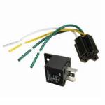
Automotive Relays are also available at both locations:
TIP122 Darlington Pair Transistor Description and Pin Outs
The TIP122 is an NPN Darlington pair transistor. As an NPN transistor, its base requires a voltage more positive than its emitter to allow significant current to flow from the collector to the emitter. The Darlington configuration provides very high current gain, meaning a small base current from the Arduino can control a much larger collector current.
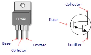
- Pin 1 (Base): Connects to the Arduino output pin (through a current-limiting resistor).
- Pin 2 (Collector): Connects to one side of the relay coil.
- Pin 3 (Emitter): Connects to Ground (GND).
The TIP122 can typically handle up to 5 amps of continuous collector current and voltages up to 100V between collector and emitter, making it suitable for driving standard automotive relays.
The Automotive (Bosch Style) Relay Pin Outs and Description
These common "cube" relays come in various voltage and current ratings. A typical 12V automotive relay might have contact ratings like 20A/30A or 30A/40A. The two numbers usually refer to the Normally Closed (NC) and Normally Open (NO) contact ratings, respectively.
The coil resistance determines the current needed to activate the relay. A typical 12V relay coil might have around 80-100 ohms resistance, drawing about 120-150 mA (I = V/R = 12V / ~90Ω ≈ 0.133A or 133mA). This current is far too high for a direct Arduino pin connection but well within the TIP122's capability.
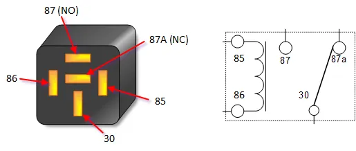
- Pin 85: One side of the relay coil. Typically connected to the transistor's collector.
- Pin 86: The other side of the relay coil. Typically connected to the positive (+) 12V supply.
- Pin 30: Common contact. Connects to the power source for the device being switched.
- Pin 87: Normally Open (NO) contact. Connects to Pin 30 when the relay coil is energized.
- Pin 87a: Normally Closed (NC) contact (not present on all relays). Connects to Pin 30 when the relay coil is *not* energized.
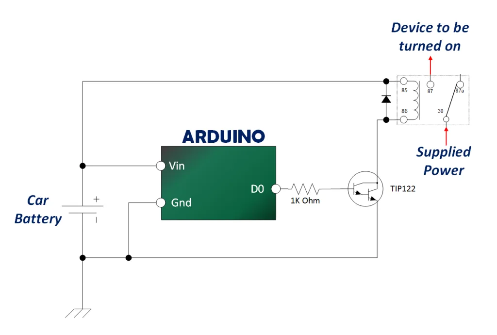
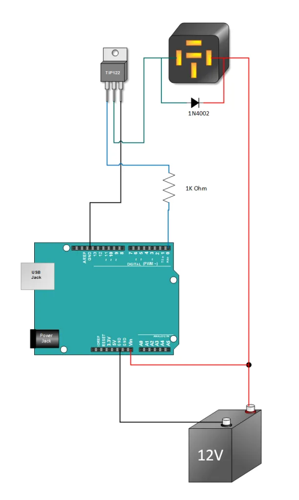
Arduino TIP122 Relay Schematic and Circuit Description
In the schematic below, a HIGH signal from the Arduino output pin (e.g., D7) goes through a current-limiting resistor (R1, typically 1kΩ) to the base of the TIP122 (Q1). This forward-biases the transistor, allowing current to flow from its collector (connected to relay pin 85) to its emitter (connected to GND).
This current flow through the relay coil (pins 85 and 86) creates a magnetic field, pulling the relay's internal switch. This connects the Common terminal (pin 30) to the Normally Open terminal (pin 87), completing the circuit for the load (e.g., a 12V lamp).
The diode (D1) connected across the relay coil (pins 85 and 86) is a crucial "flyback" or "snubber" diode. It protects the transistor from the voltage spike generated when the relay coil's magnetic field collapses as it turns off. **Ensure the diode's banded end (cathode) is connected to the positive side of the coil (pin 86).**
Arduino TIP122 Automotive Relay Tutorial
This example builds the circuit shown above and uses a simple Arduino sketch to turn the relay on and off repeatedly.
Build the Arduino Circuit
Wire the components according to the schematic. Pay close attention to the TIP122 pinout (Base, Collector, Emitter) and the diode orientation (banded end towards +12V).
Copy, Paste and Upload the Sketch.
You may wish to disconnect the 12V power supply before uploading the sketch.
// Emre's Bench
// TIP122 Arduino Relay Tutorial

const int relayControlPin = 7; // Arduino digital pin connected to TIP122 base resistor

void setup() {
  // Set the relay control pin as an output
  pinMode(relayControlPin, OUTPUT);

  // Ensure the relay is initially OFF (LOW signal to NPN transistor base)
  digitalWrite(relayControlPin, LOW);

  Serial.begin(9600); // Optional: For serial monitor messages
  Serial.println("TIP122 Relay Control Test");
}

void loop() {
  Serial.println("Turning Relay ON (Pin HIGH)");
  digitalWrite(relayControlPin, HIGH); // Turn ON TIP122, energizing relay
  delay(2000);                      // Wait 2 seconds

  Serial.println("Turning Relay OFF (Pin LOW)");
  digitalWrite(relayControlPin, LOW);  // Turn OFF TIP122, de-energizing relay
  delay(2000);                      // Wait 2 seconds
}
Verify Operation
After uploading the sketch, connect the 12V power supply. You should hear the automotive relay clicking ON for 2 seconds and then OFF for 2 seconds, repeatedly.
Final Thoughts
If designing this circuit for long-term use, especially in a vehicle, directly powering the Arduino from the car battery (even via the VIN pin) is generally not recommended due to voltage fluctuations and noise. Using a dedicated, regulated 5V power supply (like a DC-DC buck converter designed for automotive use) for the Arduino is a much more robust solution.