MCP41010 Digital Potentiometer Arduino Tutorial
Providing Analog Output Control
The MCP41010 is a digital potentiometer that is controlled using the SPI (Serial Peripheral Interface) Interface. It provides a 10kΩ potentiometer that is fully adjustable using 256 steps (0-255), offering approximately 39 ohms per step.
This allows your Arduino to programmatically control resistance, which can be used, for example, to create a variable voltage output when used as a voltage divider.
Getting an MCP41010
You may purchase an MCP41010 at any of the following locations:
MCP41010 Pin Outs
The device pin outs are shown below (for the PDIP package):
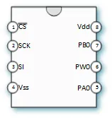
- Pin 1 (CS): Chip Select (Input, Active LOW). When LOW, the chip listens for SPI commands.
- Pin 2 (SCK): Serial Clock (Input). Clock input from the Arduino SPI master.
- Pin 3 (SI): Serial Data Input (Input). Receives commands from the Arduino when CS is LOW. Sometimes labeled SDI or MOSI.
- Pin 4 (Vss): Negative Supply or Ground (Connect to GND).
- Pin 5 (PA0): Potentiometer Terminal A. One end of the internal resistor.
- Pin 6 (PW0): Potentiometer Wiper Output. The adjustable tap point.
- Pin 7 (PB0): Potentiometer Terminal B. The other end of the internal resistor.
- Pin 8 (Vdd): Positive Supply Voltage (Connect to 5V or 3.3V, depending on your Arduino).
The Potentiometer Output
The position of the internal wiper connecting PW0 (Pin 6) to a point along the resistance between PA0 (Pin 5) and PB0 (Pin 7) is controlled via SPI commands. With a fixed voltage applied across terminals A and B (e.g., 5V on A, GND on B), sending SPI commands to change the wiper position (0-255) will change the voltage output at the wiper pin (PW0).
MCP41010 Arduino Tutorial
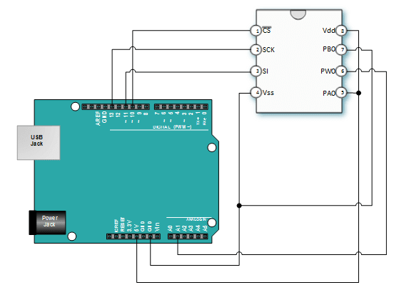
This tutorial connects the MCP41010 to the Arduino via the standard SPI pins. Potentiometer terminals A (PA0) and B (PB0) are connected to the Arduino 5V and Ground, respectively, creating a voltage divider. The wiper (PW0) output is connected to Arduino Analog Pin A1 to read the resulting voltage.
The sketch cycles the digital potentiometer through all 256 possible wiper positions, reading the voltage at the wiper for each step and printing the level and corresponding voltage to the Serial Monitor.
Connections to the Arduino
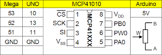
Connect your Arduino to the MCP41010 potentiometer as shown below (pins for Arduino Uno/Nano):
- MCP41010 Pin 1 (CS) to Arduino Pin 10 (SS/CS)
- MCP41010 Pin 2 (SCK) to Arduino Pin 13 (SCK)
- MCP41010 Pin 3 (SI) to Arduino Pin 11 (MOSI)
- MCP41010 Pin 4 (Vss) to Arduino GND
- MCP41010 Pin 5 (PA0) to Arduino 5V
- MCP41010 Pin 6 (PW0) to Arduino Analog Pin A1
- MCP41010 Pin 7 (PB0) to Arduino GND
- MCP41010 Pin 8 (Vdd) to Arduino 5V
Arduino Sketch
This code uses the standard Arduino SPI library to communicate with the MCP41010.
/*
  Emre's Bench - MCP41010 Digital Potentiometer Tutorial
  Demonstrates controlling the MCP41010 via SPI and reading the wiper voltage.
*/

#include <SPI.h>

const int chipSelectPin = 10;    // SPI Chip Select pin (SS on Uno/Nano)
const int wiperReadPin = A1;     // Analog pin to read the wiper voltage

void setup() {
  // Set the Chip Select pin as an output
  pinMode (chipSelectPin, OUTPUT);
  // Set the default SS pin as an output (required by SPI library even if not used for CS)
  pinMode (SS, OUTPUT);

  Serial.begin(9600);
  SPI.begin(); // Initialize SPI library

  Serial.println("MCP41010 Test");
}

void loop() {
  int rawVoltage = 0;
  float voltage = 0.0;

  Serial.println("Sweeping Wiper UP (0 to 255):");
  // Move the potentiometer wiper from 0 to 255
  for (int level = 0; level <= 255; level++) {
    MCP41010Write(level); // Send the new wiper position
    delay(50); // Small delay for stability and readability

    // Read the voltage at the wiper
    rawVoltage = analogRead(wiperReadPin);
    voltage = (rawVoltage * 5.0) / 1023.0; // Convert ADC reading to voltage (assuming 5V reference)

    Serial.print("Level = ");
    Serial.print(level);
    Serial.print("\t Raw = ");
    Serial.print(rawVoltage);
    Serial.print("\t Voltage = ");
    Serial.println(voltage, 3); // Print voltage with 3 decimal places
  }

  delay(2000); // Wait a couple seconds

  Serial.println("\nSweeping Wiper DOWN (255 to 0):");
  // Now move potentiometer wiper back down
  for (int level = 255; level >= 0; level--) {
    MCP41010Write(level);
    delay(50);

    rawVoltage = analogRead(wiperReadPin);
    voltage = (rawVoltage * 5.0) / 1023.0;

    Serial.print("Level = ");
    Serial.print(level);
    Serial.print("\t Raw = ");
    Serial.print(rawVoltage);
    Serial.print("\t Voltage = ");
    Serial.println(voltage, 3);
  }
   delay(2000); // Wait before repeating
}

// Function to send command and value to MCP41010
void MCP41010Write(byte value) {
  // Take the Chip Select pin LOW to select the chip
  digitalWrite(chipSelectPin, LOW);

  // Send the command byte (0x11 for writing to Potentiometer 0)
  SPI.transfer(B00010001);
  // Send the value byte (0-255) for the wiper position
  SPI.transfer(value);

  // Take the Chip Select pin HIGH to release the chip
  digitalWrite(chipSelectPin, HIGH);
}
Sketch Results
Open the Serial Monitor (9600 baud). You should see the output voltage smoothly changing as the `level` value cycles from 0 to 255 and back down. The voltage should range from approximately 0V (at level 0) to 5V (at level 255).
Note: Due to internal resistances and tolerances, the minimum and maximum voltages might not be exactly 0V and 5V. The voltage change per step should be roughly consistent (around 5V / 256 steps ≈ 19.5 mV/step).