Small DC Motor Speed Control with PWM
Simple DC Motor with an Arduino – Part 2
PWM Speed Control
Generally, you can control the speed of a DC motor by tweaking the voltage. The higher the voltage, the higher the speed. Conversely, lowering the voltage slows things down.
In the case of a 5-volt DC motor, applying 5V would give us full speed, while 2.5 volts would give us a slower speed. Indeed, back in the day, a simple potentiometer as part of a voltage divider would often be used to apply a variable voltage to the motor directly.
In the age of microcontrollers, however, the most common method of controlling DC motor speed is to use Pulse Width Modulation (PWM).
With an Arduino, we use pins capable of providing a pulse width modulated output (marked with `~` on many boards, like pins 3, 5, 6, 9, 10, 11 on an Uno) and we use the function `analogWrite()` to control the amount of time the motor voltage is effectively on.
Fundamentally, `analogWrite(pin, value)` specifies the percentage of time (duty cycle) the output pin will be HIGH (providing full voltage). The `value` ranges from 0 (0% duty cycle, always off) to 255 (100% duty cycle, always on).
- A value of 255 means the motor sees 5V (or the supply voltage) 100% of the time (full speed).
- A value of 128 means the motor sees 5V approximately 50% of the time (roughly half speed).
- A value of approx. 204 (80% of 255) means the motor sees 5V 80% of the time (roughly 80% speed).
- A value of 0 means the motor sees 0V (off).
While the pin rapidly switches between HIGH and LOW, the motor effectively responds to the *average* voltage.
Using the Arduino analogWrite Command
Once we’ve set the `pinMode` to `OUTPUT`, it's just a matter of using the `analogWrite(pin, value)` command to specify the duty cycle (0-255) and thus control the average voltage supplied to the motor.
For example, to set the motor pin (let's say pin 3) to roughly 80% speed:
int motorPin = 3;
int speedValue = 204; // Approximately 80% of 255

pinMode(motorPin, OUTPUT);
analogWrite(motorPin, speedValue);
The Parts and Hook Up
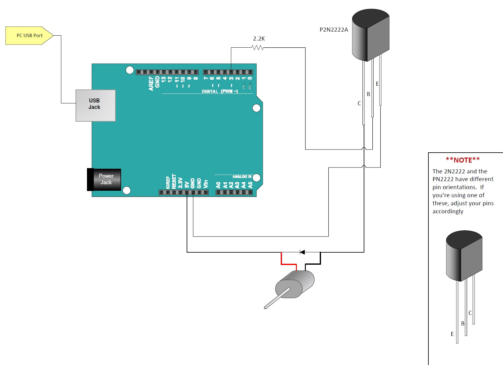
You’re going to use the same hookup found in Simple DC Motor with an Arduino – Part 1. Ensure the Arduino pin connected to the transistor base (via the resistor) is a PWM-capable pin (e.g., pin 3).
The Arduino PWM Motor Code
This sketch demonstrates switching the motor between full speed (`analogWrite(motorDrive, 255)`) and half speed (`analogWrite(motorDrive, 128)`).
// Emre's Bench - Small DC Motor with PWM Speed Control

const int motorDrivePin = 3; // PWM pin connected to transistor base (via resistor)
const int timeOn = 2500;     // Amount of time motor runs at a given speed
const int timeOff = 1000;    // Amount of time motor runs at the other speed (or is off)

void setup() {
  // Set the motor control pin as an output
  pinMode(motorDrivePin, OUTPUT);
}

void loop() {
  // Run at full speed
  analogWrite(motorDrivePin, 255); // 100% duty cycle
  delay(timeOn);                   // Keep at this speed

  // Run at roughly half speed
  analogWrite(motorDrivePin, 128); // Approx 50% duty cycle
  delay(timeOff);                  // Keep at this speed

  // You could also turn it off completely:
  // analogWrite(motorDrivePin, 0); // 0% duty cycle (Off)
  // delay(timeOff);
}
Upload this sketch. The motor should run at full speed for 2.5 seconds, then slow down to about half speed for 1 second, and repeat.