Simple DC Motor with an Arduino
Motor On and Motor Off
This article shows how to use an Arduino to power a small DC motor. Fundamentally, we will use the Arduino to alternate between turning the motor on and then off.
A transistor will be used to switch the ground connection to the motor, causing it to spin when the Arduino provides a signal. This fundamental technique of using a microcontroller output pin to control a higher-power device (like a motor, which can draw more current than an Arduino pin can safely provide) via a transistor is essential.
Parts List
- P2N2222A Transistor - You could use a 2N2222 or a PN2222, but you will need to pay attention to the pins. They're pretty cheap in quantity.
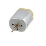
- 5V DC Motor - The 5V motor I used is common in toys and hobbies. You can buy one here
- Arduino Uno R3 - I generally use the real thing, but the clones can cost you as little as 10 bucks.
- 2.2K Resistor - Buying a single resistor is silly. Get a resistor assortment. One like this will do.
- Small Diode (e.g., 1N4001) - Used as a flyback diode. They’re so cheap that getting them in quantity makes sense. Try Here
The Connections
The diagram below shows how to connect the components. The diode is crucial – it's a "flyback" diode that protects the transistor from voltage spikes generated by the motor when it turns off.
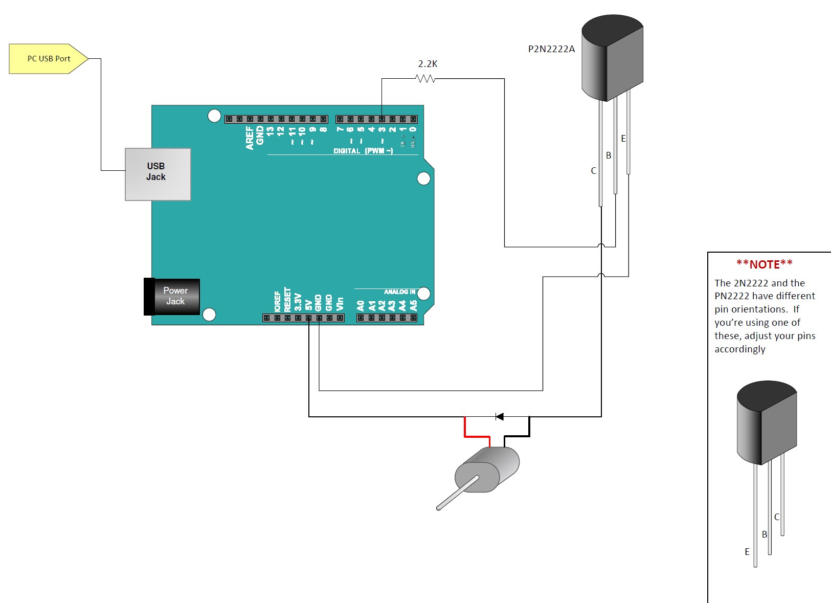
In the diagram, the transistor is used to control the motor. The Arduino sends a signal to the base of the transistor, allowing current to flow from the collector to the emitter, thus powering the motor.
- Arduino Digital Pin 3 connects through the 2.2kΩ resistor to the Base (B) pin of the P2N2222A transistor.
- The Emitter (E) pin of the transistor connects to Arduino GND.
- One terminal of the DC motor connects to the Collector (C) pin of the transistor.
- The other terminal of the DC motor connects to the Arduino 5V pin.
- The 1N4001 diode is connected *across* the motor terminals. The banded end (cathode) connects to the 5V side, and the non-banded end (anode) connects to the transistor collector side. **Ensure correct diode orientation!**
- Arduino GND connects to the common ground rail.
The Arduino Motor Sketch
This sketch turns the motor on for 2.5 seconds and then off for 1 second, repeating indefinitely.
// Emre's Bench - Simple Small DC Motor Control

const int motorDrivePin = 3;  // Arduino digital pin connected to the transistor base (via resistor)
const int onTime = 2500;      // Amount of time motor is ON (in milliseconds)
const int offTime = 1000;     // Amount of time motor is OFF (in milliseconds)

void setup() {
  // Set the motor control pin as an output
  pinMode(motorDrivePin, OUTPUT);
  // Ensure motor is off initially
  digitalWrite(motorDrivePin, LOW);
}

void loop() {
  // Turn the motor ON
  digitalWrite(motorDrivePin, HIGH); // Send HIGH signal to transistor base, allowing current to flow
  delay(onTime);                     // Keep the motor on for the specified duration

  // Turn the motor OFF
  digitalWrite(motorDrivePin, LOW);  // Send LOW signal to transistor base, stopping current flow
  delay(offTime);                    // Keep the motor off for the specified duration
}
Upload this sketch to your Arduino. The small DC motor should turn on for 2.5 seconds and then off for 1 second, repeatedly.