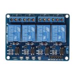
5 Volt 4 Channel Arduino Relay Module User Manual
The Basics
This relay module allows you to combine the processing power of the Arduino with devices that use higher current and/or different voltages. It does so by providing four optically isolated relays, each rated for up to 10A at 250VAC or 10A at 30VDC (check the rating printed on your specific relays).
Each relay has a Normally Open (NO), Normally Closed (NC), and Common (COM) terminal, allowing you to control:
- AC Appliances (Lamps, Fans, etc. - **Use extreme caution when working with mains voltage!**)
- DC Motors
- Lights (DC or AC)
- Other high-power circuits
Relay Module Inputs
The module requires power and control signals:
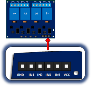
- VCC: Connects to the 5V supply from the Arduino (or a separate 5V supply if using the jumper - see schematic/notes below).
- GND: Connects to the Arduino GND.
- IN1, IN2, IN3, IN4: These are the control inputs for each relay. Applying a LOW signal (Ground) to one of these pins typically energizes the corresponding relay (activates it). Applying a HIGH signal (5V) or leaving it floating de-energizes the relay.
- JD-VCC & VCC Jumper: Many modules have a jumper connecting JD-VCC and VCC.
- With Jumper (Common): The relays are powered by the same 5V supply connected to VCC (from the Arduino). This is simpler wiring but draws more current from the Arduino's 5V regulator.
- Without Jumper: You MUST provide a separate 5V power supply to the JD-VCC pin to power the relay coils. VCC still connects to Arduino 5V (to power the optocouplers), and the GND from the separate supply must connect to the Arduino GND. This isolates the Arduino's power supply from the potentially noisy relay coils.
Relay Module Outputs
Each of the four relays provides three screw terminals for connecting the load you want to control:
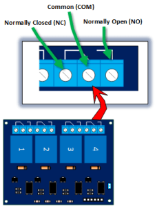
- COM (Common): This is the terminal that switches between NC and NO.
- NC (Normally Closed): This terminal is connected to COM when the relay is *not* energized (input pin is HIGH).
- NO (Normally Open): This terminal is connected to COM when the relay *is* energized (input pin is LOW).
You typically connect your load circuit through the COM terminal and either the NO or NC terminal, depending on whether you want the circuit to be complete when the relay is activated or deactivated.
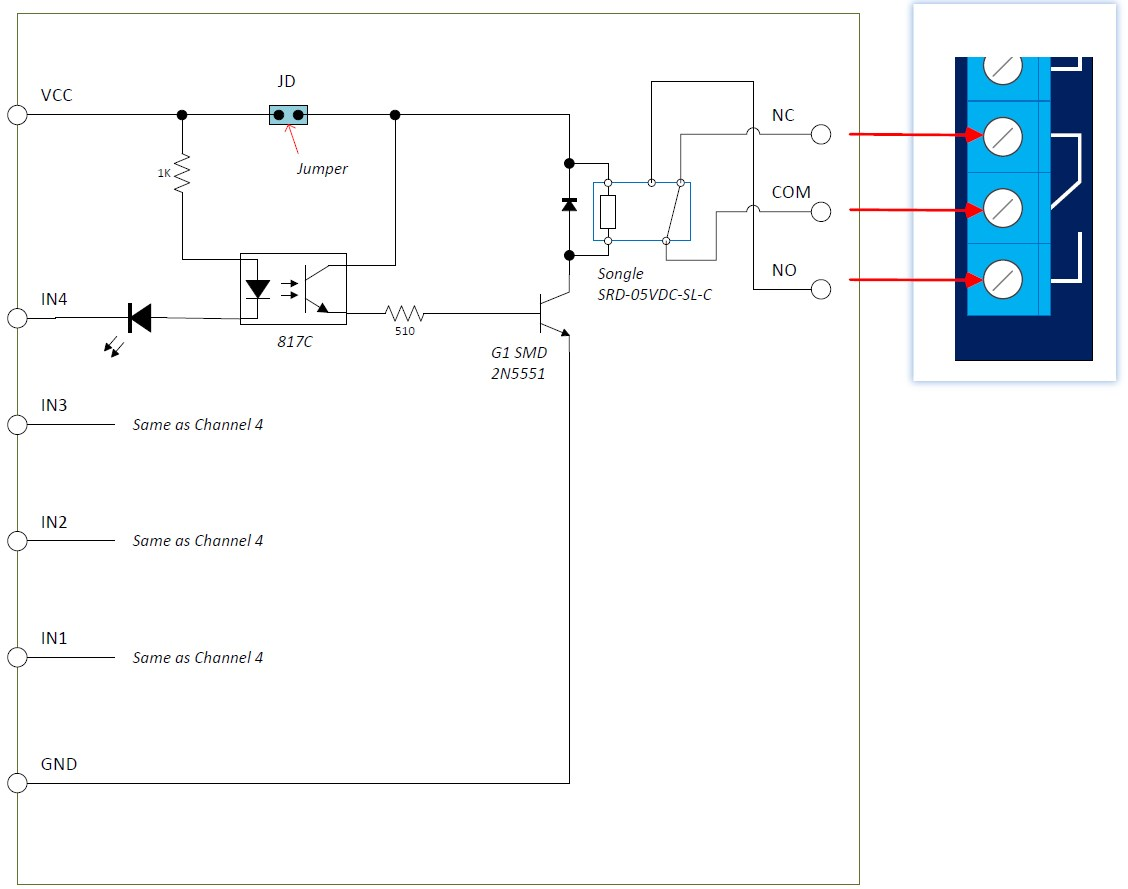
Module Schematic
Fundamentally, this board contains four similar, optically isolated relay driver circuits. Other than potentially sharing the VCC/JD-VCC line (depending on the jumper), the control inputs and relay outputs are separate. See the typical schematic below (component values may vary slightly between manufacturers):
Typical Connection to an Arduino
The drawing below shows a typical connection controlling an AC light bulb. **WARNING: Working with AC mains voltage is dangerous. Ensure you understand the risks and take appropriate safety precautions. If unsure, do not attempt AC wiring.**
This example assumes the JD-VCC/VCC jumper is **in place**, powering the relays from the Arduino 5V supply.
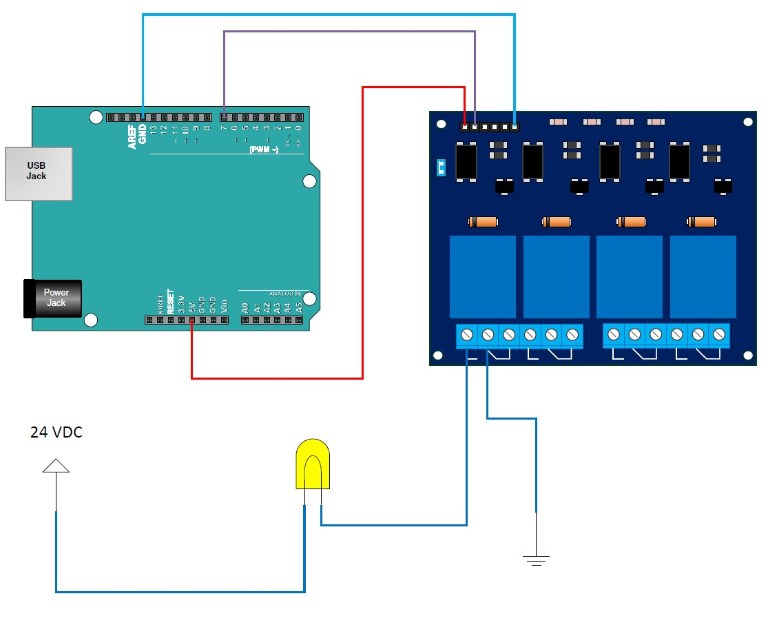
- Relay Module VCC to Arduino 5V
- Relay Module GND to Arduino GND
- Relay Module IN1 to Arduino Digital Pin 7 (or any other digital pin)
- AC Live wire connects to Relay 1 COM terminal.
- AC Light Bulb one terminal connects to Relay 1 NO terminal.
- AC Light Bulb other terminal connects to AC Neutral wire.
In this configuration, when Arduino Pin 7 is set LOW, the relay energizes, the NO contact closes, and the light turns ON. When Pin 7 is set HIGH, the relay de-energizes, the NO contact opens, and the light turns OFF.
Sample Sketch
This sketch will turn on the relay connected to Pin 7 for 10 seconds, then turn it off for 10 seconds, repeating indefinitely.
// Emre's Bench - 4 Channel Relay Module Example

const int relayPin1 = 7; // Arduino pin connected to IN1

void setup() {
  // Set the relay control pin as an output
  pinMode(relayPin1, OUTPUT);

  // Important: Initialize relay to OFF state (HIGH signal for active-low modules)
  // This prevents the relay from briefly turning on during Arduino startup
  digitalWrite(relayPin1, HIGH);

  Serial.begin(9600); // Optional: For status messages
  Serial.println("Relay Test Starting...");
}

void loop() {
  Serial.println("Turning Relay ON (Pin LOW)");
  digitalWrite(relayPin1, LOW); // Energize the relay (Active LOW)
  delay(10000);                 // Wait 10 seconds

  Serial.println("Turning Relay OFF (Pin HIGH)");
  digitalWrite(relayPin1, HIGH); // De-energize the relay
  delay(10000);                  // Wait 10 seconds
}