The ACS712 Current Sensor with an Arduino
Overview
The ACS712 Current Sensor is a cool little device for making current measurements. Better, its really easy to use with an Arduino.
In this sample project, I’ll show you just how easy it is to connect up, program and put to immediate use.
Other ACS712 Emre’s Bench Articles
- ACS712 User Guide Discusses the device directly.
- ACS712 AC Current Measurement shows how to measure AC current with an Arduino
- 18650 Battery Charger shows another implementation of the ACS712
- ACS758 Tutorial Shows a similar device for monster currents.
What You Will Need
- An Arduino – I used an Arduino UNO
- An ACS712 Current Sensor Module – I chose to use the 5 amp version. There are 20 amp and 30 amp versions also available. If you’re not all that familiar with this module, you can read my online user manual.
- A Load – I used a 10 Ohm potentiometer rated for 3.16A. That said, about anything will do. A light bulb or a different kind of resistor that can dissipate the current will do.
- A Power Source – I used a MingHe B3603 Power Supply because I wanted to have any easy means of validating the measurements on my Arduino. If you want to know more about this buck converter, you can read my online user manual.
- A Bench Supply – I used an HY3010E. You’ll probably have something different. That’s OK. However, if you’re going to duplicate my set up, you will want something that provides at least 12V at 2.00A (or 24 Watts).
The ACS712 Sample Project Schematic
The drawing below shows I hooked things up. I realize its a little small, but you can click on it to see a larger version. I've also include a printable PDF at the end of this article.
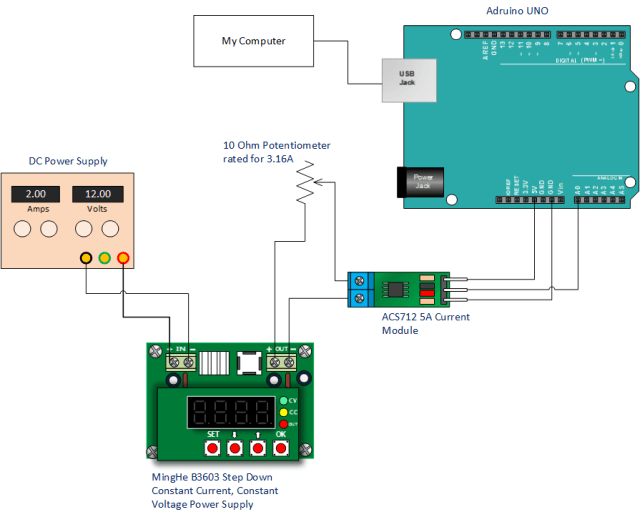
Power Supply and Potentiometer Set Up
I set the potentiometer so that it would read 10 Ohms.
On the B3603, I choose to limit the current to 1.500 amps and I set the voltage for 03.00 volts.
Once the program is running, I increase the voltage on the B3603 up to 10 volts and verify the results on the serial monitor by comparing to the indication on my B3603 current display.
The ACS712 Example Project Code
You can copy and paste the code you see below.
/*
Measuring Current Using ACS712
*/
const int analogIn = A0;
int mVperAmp = 185; // use 100 for 20A Module and 66 for 30A Module
int RawValue = 0;
int ACSoffset = 2500; // Assumes 5V supply and 50% offset, adjust if necessary
double Voltage = 0;
double Amps = 0;

void setup() {
 Serial.begin(9600);
}

void loop() {

 RawValue = analogRead(analogIn);
 // Convert ADC reading to millivolts based on 5V reference
 // Use 1024.0 for full range mapping (0-1023 -> 0-5V)
 Voltage = (RawValue / 1024.0) * 5000;
 // Calculate current in Amps
 Amps = ((Voltage - ACSoffset) / mVperAmp);

 Serial.print("Raw Value = " ); // shows pre-scaled value
 Serial.print(RawValue);
 Serial.print("\t mV = "); // shows the voltage measured
 Serial.print(Voltage,3); // Display mV with 3 decimal places
 Serial.print("\t Amps = "); // shows the current measured
 Serial.println(Amps,3); // Display Amps with 3 decimal places
 delay(2500); // Changed delay to 2.5 seconds

}
Basically the Arduino measures the input at the analog pin, converts it to millivolts, subtracts the offset and then finally divides it by the scale factor of the current sensor.
In other words, its nothing more than a simple Arduino voltmeter that interprets the output of the ACS712.
The program then makes use of the Arduino Serial Monitor to look at the results.
Running the Sample Project
Give it whirl once you’ve connected things up and keyed your program in.
You’ll notice that increasing the voltage increases the current.
If you’re using the B3603, you can validate your results by using the current display.
Otherwise, you can use can use ohms law as follows:
Current = Voltage You Applied / The Resistance of your Load