Arduino MCP4725 Digital to Analog Converter Tutorial
Zero to Five Volts in ~1.2 mV Increments
This could be a useful device if you need to create a programmable analog voltage output from your Arduino. The MCP4725 is a popular Digital-to-Analog Converter (DAC).
It has 12 bits of resolution and is controllable via the I2C interface.
MCP4725 Pin Outs
The VCC pin connects to the chip's VDD pin. It's important to understand that this not only supplies power to the chip but also acts as the voltage reference for the DAC output.
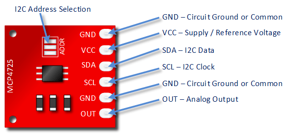
- VCC: Power supply and Voltage Reference (Connect to Arduino 5V or 3.3V).
- GND: Ground connection (Connect to Arduino GND).
- SCL: I2C Clock line (Connect to Arduino SCL - A5 on Uno/Nano).
- SDA: I2C Data line (Connect to Arduino SDA - A4 on Uno/Nano).
- VOUT: Analog Voltage Output pin.
- A0 (on some boards): Address select pin. Usually tied LOW via a resistor on the board for default address (0x62 or 0x60). Can sometimes be jumpered or cut to change the address if needed (e.g., to 0x63).
MCP4725 Specification Notes
Arduino MCP4725 DAC Resolution
This is a 12-bit DAC. This means it accepts a digital input value from 0 to 4095 (which is 212 possible steps) to produce a corresponding analog voltage output.
- A digital value of 0 corresponds to an output voltage of 0V.
- A digital value of 4095 corresponds to an output voltage equal to the VCC supply voltage (full scale).
The supply voltage (VCC) can range from 2.7V to 5.5V. The voltage resolution (the smallest voltage change per step) depends on this VCC value:
1 LSB = VCC / 4096
For example:
- With VCC = 5.0V, 1 LSB ≈ 5.0V / 4096 ≈ 0.00122V or 1.22mV.
- With VCC = 3.3V, 1 LSB ≈ 3.3V / 4096 ≈ 0.00081V or 0.81mV.
Using a lower VCC voltage provides finer voltage resolution, which might be beneficial if your target output range doesn't exceed that lower voltage.
MCP4725 Power Requirements
With no load connected to the VOUT pin, the MCP4725 draws very little current (typically around 0.21 mA, max 0.4 mA).
MCP4725 Output Current Limits
The VOUT pin can source or sink a maximum of 25 mA. This is generally **not enough** to directly power devices like motors or high-power LEDs. You would typically use the DAC's output voltage to control another component (like a transistor or op-amp) capable of handling higher currents.
Arduino MCP4725 DAC Tutorial
Download and Install the Adafruit MCP4725 Library
To simplify using the MCP4725, it's highly recommended to install Adafruit's library. You can find it here on GitHub or install it via the Arduino IDE's Library Manager (Sketch -> Include Library -> Manage Libraries... -> search for "Adafruit MCP4725").
If you're not familiar with installing Arduino libraries, check the official Arduino guide.
Connecting Your Arduino to the MCP4725
This module uses I2C, requiring only four wires:
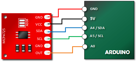
- MCP4725 VCC to Arduino 5V
- MCP4725 GND to Arduino GND
- MCP4725 SDA to Arduino SDA (A4 on Uno/Nano)
- MCP4725 SCL to Arduino SCL (A5 on Uno/Nano)
- MCP4725 VOUT to Arduino Analog Pin A0 (to measure the output)
Get Your MCP4725 I2C Address
Most common MCP4725 breakout boards use a default I2C address of **0x62** (Adafruit standard) or **0x60**. If the provided code doesn't work, the address might be different.
You can use an I2C Scanner Sketch to find the correct address of your connected module.
Copy Paste and Upload the MCP4725 Tutorial Code
This sketch uses the Adafruit library to cycle the DAC output from 0 to 4095 (full scale) and back down. It also reads the DAC's output voltage using an Arduino analog input pin (A0) for comparison.
// Emre's Bench
// MCP4725 DAC Tutorial using Adafruit Library

#include <Wire.h>
#include <Adafruit_MCP4725.h>

Adafruit_MCP4725 dac; // Default constructor using address 0x62
// For boards with address 0x60: Adafruit_MCP4725 dac(0x60);

const int dacReadPin = A0; // Analog pin to read DAC output voltage

void setup(void) {
  Serial.begin(9600);
  while (!Serial) {
    ; // Wait for serial port
  }
  Serial.println("MCP4725 DAC Test");

  // Try initializing the DAC. Use address 0x62 by default
  // If using 0x60, uncomment the line below and comment the default one
  if (!dac.begin(0x62)) {
  //if (!dac.begin(0x60)) {
    Serial.println("Failed to find MCP4725 chip. Check wiring and I2C address!");
    while (1);
  }
  Serial.println("MCP4725 Found!");
}

void loop(void) {
    uint16_t dacValue; // Use uint16_t for 12-bit value (0-4095)
    int adcValueRead = 0;
    float voltageRead = 0;
    float dacExpectedOutput = 0;

    Serial.println("\nSweeping DAC Output UP:");
    // Sweep up
    for (dacValue = 0; dacValue < 4096; dacValue += 15) { // Increment faster

      dacExpectedOutput = (5.0 / 4095.0) * dacValue; // Calculate expected VOUT (using 4095 for max)
      dac.setVoltage(dacValue, false); // Set DAC output, false = don't store in EEPROM

      delay(50); // Allow voltage to settle and slow down output

      adcValueRead = analogRead(dacReadPin); // Read voltage with Arduino ADC
      voltageRead = (adcValueRead * 5.0) / 1023.0; // Convert Arduino ADC reading to voltage

      Serial.print("DAC Value: "); Serial.print(dacValue);
      Serial.print("\tExpected V: "); Serial.print(dacExpectedOutput, 3);
      //Serial.print("\tADC Raw: "); Serial.print(adcValueRead); // Uncomment for debugging
      Serial.print("\tMeasured V: "); Serial.println(voltageRead, 3);
    }

    delay(1000); // Pause at the top

     Serial.println("\nSweeping DAC Output DOWN:");
    // Sweep down
     for (dacValue = 4095; dacValue > 15 ; dacValue -= 15) { // Decrement faster, stop before 0

      dacExpectedOutput = (5.0 / 4095.0) * dacValue;
      dac.setVoltage(dacValue, false);

      delay(50);

      adcValueRead = analogRead(dacReadPin);
      voltageRead = (adcValueRead * 5.0) / 1023.0;

      Serial.print("DAC Value: "); Serial.print(dacValue);
      Serial.print("\tExpected V: "); Serial.print(dacExpectedOutput, 3);
      //Serial.print("\tADC Raw: "); Serial.print(adcValueRead); // Uncomment for debugging
      Serial.print("\tMeasured V: "); Serial.println(voltageRead, 3);

       // Check if dacValue will underflow before next iteration
        if (dacValue < 15) break;
    }
     // Set to 0 explicitly at the end
    dac.setVoltage(0, false);
    delay(50);
    adcValueRead = analogRead(dacReadPin);
    voltageRead = (adcValueRead * 5.0) / 1023.0;
    Serial.print("DAC Value: 0");
    Serial.print("\tExpected V: 0.000");
    Serial.print("\tMeasured V: "); Serial.println(voltageRead, 3);

    delay(2000); // Pause at the bottom
}
Important: Make sure the I2C address in `dac.begin(0x62);` matches the actual address of your module (likely 0x62 or 0x60). Change it if necessary.
Verify Your MCP4725 Tutorial Output
Open the Serial Monitor at 9600 baud. After initialization, you should see lines printing the DAC value sent (0-4095), the theoretically expected voltage, and the voltage measured by the Arduino's A0 pin.
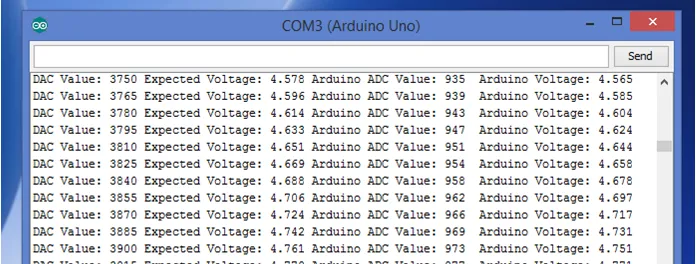
The "Expected Voltage" and "Measured V" should track each other closely, ranging from near 0V to near 5V. Minor differences (~10-30mV) are expected due to the tolerance of the components and the limited accuracy of both the DAC and the Arduino's ADC, especially when using the standard 5V pin as a reference (which isn't perfectly stable).