Arduino HC-SR501 Motion Sensor Tutorial
The HC-SR501 Passive Infrared (PIR) Motion Sensor
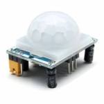
This motion sensor module uses the LHI778 Passive Infrared Sensor and the BISS0001 IC to control how motion is detected.
The module features adjustable sensitivity that allows for a motion detection range from 3 meters to 7 meters.
The module also includes time delay adjustments and trigger selection that allow for fine tuning within your application.
This article discusses these various functions and demonstrates how to integrate them for use with your Arduino.
HC-SR501 Pin Outs and Controls
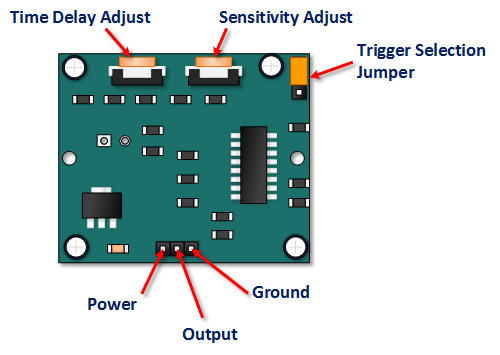
The pin-outs and controls for this device are shown in the picture below and described in the following table.
| Pin or Control | Function |
|---|---|
| Time Delay Adjust | Sets how long the output remains high after detecting motion (Approx. 5 seconds to 5 minutes). |
| Sensitivity Adjust | Sets the detection range (Approx. 3 meters to 7 meters). |
| Trigger Selection Jumper | Set for single (H) or repeatable (L) triggers. See description below. |
| Ground pin | Ground connection (0V). |
| Output Pin | Outputs LOW when no motion is detected, HIGH (3.3V) when motion is detected. |
| Power Pin | 5V to 20V DC Supply input. |
HC SR501 PIR Functional Description
The SR501 detects changes in infrared radiation within its detection area. If these changes are interpreted as motion (based on settings), it sets its output pin HIGH.
Device Initialization
The device requires nearly a minute to initialize after power-up. During this period, it can and often will output false detection signals. Your circuit or code logic needs to account for this initialization time (e.g., ignore readings for the first 60 seconds).
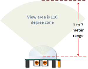
Device Area of Detection
The device detects motion within a cone of approximately 110-120 degrees, with an adjustable range of 3 to 7 meters.
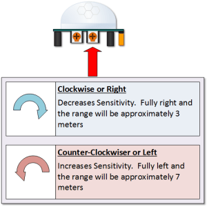
PIR Range (Sensitivity) Adjustment
As mentioned, the adjustable range is from approximately 3 meters (minimum sensitivity) to 7 meters (maximum sensitivity). Turning the potentiometer adjusts this sensitivity. Clockwise typically increases sensitivity.
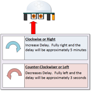
Time Delay Adjustment
This potentiometer adjusts how long the output pin remains HIGH after motion is last detected. The range is approximately 3 seconds (minimum delay) to 5 minutes (maximum delay). Clockwise typically increases the delay.
Blocking Time After Output Goes LOW – IMPORTANT
After the output pin goes LOW (either after the set time delay expires or in non-repeatable mode), the sensor enters a brief blocking period (typically 2-3 seconds) during which it will *not* detect motion. This prevents rapid re-triggering.
For Example (Single Trigger Mode, 5-second delay):
- Motion is detected. Output goes HIGH for 5 seconds.
- After 5 seconds, output goes LOW.
- The sensor enters the blocking period (approx. 3 seconds). Motion is *not* detected during this time.
- After the blocking period, the sensor is ready to detect motion again.
Trigger Mode Selection Jumper
This jumper selects how the sensor behaves when motion continues during the delay period.
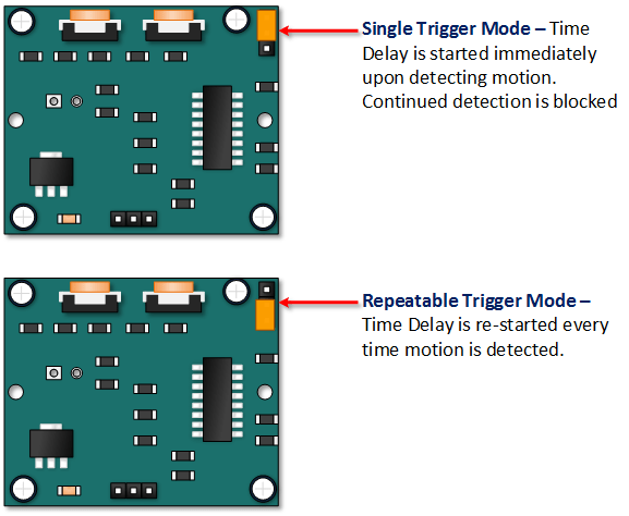
- Non-Repeatable Trigger (H position - default): When motion is detected, the output goes HIGH for the set time delay period. It then goes LOW, enters the blocking period, and only then can detect new motion. Continuous motion during the delay period does *not* extend the HIGH time. This is sometimes called "single trigger" mode.
- Repeatable Trigger (L position): When motion is detected, the output goes HIGH. If motion continues to be detected *during* the time delay period, the delay timer resets. The output will remain HIGH as long as motion is continuously detected, plus the delay time after the *last* motion stops.
HC-SR501 Dance Floor Application Examples
Imagine you want to control lighting on a dance floor based upon where the dancers are dancing. Understanding how the time delay and trigger mode interact is crucial.
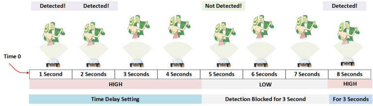
Example One: Non-Repeatable Trigger
In this first example, the time delay is set to three seconds and the trigger mode is set to non-repeatable (H position). As you can see in the illustration below, the output goes LOW even if motion continues, due to the time delay expiring followed by the blocking period. Motion is effectively missed during these intervals.

Example Two: Repeatable Trigger
In the next example, the time delay is still three seconds, but the trigger is set to repeatable (L position). Now, the output stays HIGH as long as motion is present because each detection resets the 3-second timer. Only after the last motion stops does the 3-second delay count down, followed by the ~3-second blocking period.
As mentioned previously, you can often achieve better control by setting the hardware delay to minimum and managing the "lights on" duration within your Arduino code, especially if you need responsiveness faster than the sensor's blocking period allows.
Arduino HC-SR501 Motion Sensor Tutorial
Connect Your Arduino to the HC-SR501
This requires only three wires:
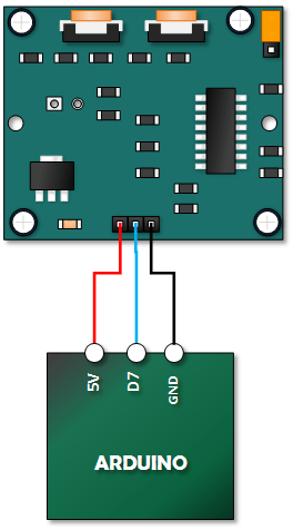
- HC-SR501 VCC Pin to Arduino 5V Pin
- HC-SR501 GND Pin to Arduino GND Pin
- HC-SR501 OUT Pin to Arduino Digital Pin 7 (or any other digital pin)
Copy, Paste and Upload the Tutorial Sketch
This simple sketch reads the state of the PIR sensor's output pin and turns the Arduino's built-in LED (connected to Pin 13) ON when motion is detected (HIGH signal) and OFF when no motion is detected (LOW signal).
Remember the initialization period! After uploading the sketch and powering on, wait about 60 seconds before expecting reliable motion detection.
// Emre's Bench
// HC-SR501 Motion Detector Sample Sketch

const int ledPin = 13;  // LED on Pin 13 of Arduino (Built-in LED)
const int pirPin = 7;   // Input Pin for HC-SR501 Output

int pirValue; // Variable to store the PIR sensor status

void setup() {
  pinMode(ledPin, OUTPUT);
  pinMode(pirPin, INPUT);
  Serial.begin(9600); // Optional: for serial monitor debugging

  Serial.println("HC-SR501 Motion Sensor Test");
  Serial.println("Initializing sensor...");

  // It's good practice to ensure the pin is initially low
  digitalWrite(ledPin, LOW);

  // Give the sensor time to calibrate (approx. 60 seconds)
  // You might want a more sophisticated way to handle this in a real project
  delay(60000);
  Serial.println("Sensor Ready!");
}

void loop() {
  pirValue = digitalRead(pirPin); // Read the PIR sensor output

  if (pirValue == HIGH) {          // If motion is detected
    digitalWrite(ledPin, HIGH);    // Turn the LED on
    Serial.println("Motion detected!"); // Optional: Print to Serial Monitor
    // Add any other actions you want to perform when motion is detected here
  } else {                         // If no motion is detected
    digitalWrite(ledPin, LOW);     // Turn the LED off
    // Add any actions for when no motion is detected (or just do nothing)
  }

  // Small delay to prevent spamming the serial monitor if using it
  delay(100);
}
After uploading, open the Serial Monitor (set to 9600 baud). Wait for the "Sensor Ready!" message. Then, move your hand in front of the sensor. The Arduino's built-in LED should light up, and you should see "Motion detected!" in the Serial Monitor. When you stop moving, the LED should turn off after the sensor's set time delay (and blocking period) expires.