Keyes KY-040 Arduino Rotary Encoder Tutorial
The Keyes KY-040 Rotary Encoder
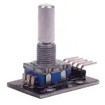
The Keyes KY-040 rotary encoder is a rotary input device (as in, a knob) that provides an indication of how much the knob has been rotated AND what direction it is rotating in.
It's a great device for stepper and servo motor control. You could also use it to control devices like digital potentiometers or navigate menus.
How to Get One
These are sold in several places, including the vendors below. Each of these vendor offers solid buyer protection through PayPal.
Rotary Encoder Basics
A rotary encoder has a fixed number of positions (detents) per revolution. These positions are easily felt as small "clicks" as you turn the encoder shaft. The Keyes module typically has 20 or 30 positions per revolution.
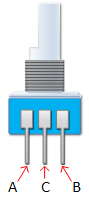
On one side of the encoder switch itself there are three pins, often referred to as A, B, and C (Common). Inside the encoder, there are essentially two switches: one connects pin A to pin C, and the other connects pin B to C.
In each encoder detent position, both internal switches are either open or closed. Each click (moving from one detent to the next) causes these switches to change states:
- If both switches are closed, turning the encoder one position will cause both switches to open.
- If both switches are open, turning the encoder one position will cause both switches to close.
The key to detecting direction lies in the slight offset between the A and B contacts:
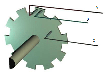
- Rotating the switch clockwise causes switch A to change state slightly *before* switch B.
- Rotating the switch counterclockwise causes switch B to change state slightly *before* switch A.
If we represent the opening and closing as digital waveforms (HIGH = open, LOW = closed, assuming pull-ups and common connected to ground), they look like quadrature signals:
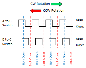
By monitoring one pin (e.g., A) and checking the state of the other pin (B) when A changes, we can determine the direction:
- If A changes state, and B is *different* from A's new state, it's clockwise.
- If A changes state, and B is the *same* as A's new state, it's counterclockwise.
KY-040 Module Pin Outs
The pin outs for the Keyes KY-040 module board are identified below:
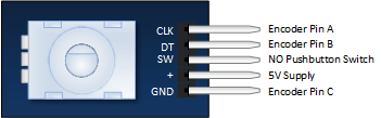
- CLK: Output A (Connects to an Arduino digital pin, often an interrupt pin).
- DT: Output B (Connects to an Arduino digital pin, often an interrupt pin).
- SW: Push button switch output (Connects to an Arduino digital pin). Goes LOW when the shaft is pressed.
- +: 5V Power Supply Input.
- GND: Ground connection.
The module includes pull-up resistors on CLK, DT, and SW, so these pins output a HIGH signal when the internal switches are open (or button not pressed) and LOW when closed (or button pressed).
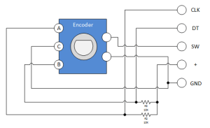
Keyes Rotary Encoder Schematic
A schematic for this module is provided below. R1, R2, and R3 are pull-up resistors.
Keyes KY-040 Evaluation Circuit
Successfully implementing the Rotary Encoder requires a clear understanding of everything discussed. If you're still a little fuzzy, you may wish to build the evaluation circuit below using LEDs to visualize the state changes:
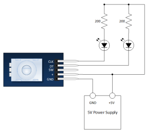
VERY SLOWLY rotate the encoder shaft both clockwise and counterclockwise. Notice which LEDs (representing CLK and DT states) change first with rotation.
KY-040 Arduino Tutorial
Module Connection to the Arduino
Pretty straightforward. Connect the module to your Arduino as follows:
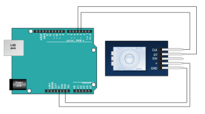
- Module GND to Arduino GND
- Module + to Arduino 5V
- Module SW to Arduino Digital Pin 2
- Module DT to Arduino Digital Pin 4
- Module CLK to Arduino Digital Pin 3
The Arduino Sketch
This is a simple sketch that shows how to count the encoder position and determine the direction of rotation by polling the pins. It does not include switch debouncing or use interrupts. A fully developed application might need these for more robust performance, especially if the Arduino is busy with other tasks or the encoder is turned quickly.
// Emre's Bench - KY-040 Rotary Encoder Basic Tutorial

const int pinA = 3; // Connected to CLK on KY-040
const int pinB = 4; // Connected to DT on KY-040
// const int pinSW = 2; // Connected to SW on KY-040 (Switch Pin - Not used in this basic example)

int encoderPosCount = 0; // Counter for encoder position
int pinALast;            // Stores the previous state of CLK pin
int aVal;                // Stores the current state of CLK pin
boolean bCW;             // Flag to indicate direction (true = Clockwise)

void setup() {
  pinMode (pinA, INPUT);
  pinMode (pinB, INPUT);
  // pinMode (pinSW, INPUT_PULLUP); // Use pullup for the switch if needed

  // Read the initial state of pinA
  pinALast = digitalRead(pinA);

  Serial.begin (9600);
  Serial.println("KY-040 Rotary Encoder Test");
}

void loop() {
  aVal = digitalRead(pinA); // Read the current state of CLK pin

  if (aVal != pinALast) { // If the state has changed, the knob was rotated
    // Check the state of the DT pin to determine direction
    if (digitalRead(pinB) != aVal) {
      // DT state is different from CLK state: Clockwise rotation
      encoderPosCount++;
      bCW = true;
    } else {
      // DT state is the same as CLK state: Counter-Clockwise rotation
      encoderPosCount--;
      bCW = false;
    }

    // Print the direction and current position count
    Serial.print("Rotated: ");
    if (bCW) {
      Serial.println("Clockwise");
    } else {
      Serial.println("Counterclockwise");
    }
    Serial.print("Encoder Position: ");
    Serial.println(encoderPosCount);
  }

  pinALast = aVal; // Save the current state as the last state for the next loop iteration

  // A small delay can sometimes help stabilize readings in simple polling loops,
  // but might cause missed steps if the encoder is turned very quickly.
  // delay(1);
}
Open the Serial Monitor (at 9600 baud) after uploading. As you turn the encoder knob, you should see the position count increase or decrease and the direction printed.