Arduino Sound Detection Sensor: Tutorial and User Manual
Basic Description
This module allows you to detect when sound has exceeded a set threshold. Sound is detected via an electret microphone and fed into an LM393 comparator.
The sound level threshold is adjusted via an onboard potentiometer. When the sound level exceeds the set point, an LED on the module illuminates, and the digital output pin (OUT) is pulled LOW.
This tutorial focuses on the common three-pin version with only a digital output. Some versions may have four pins, including an analog output representing the raw microphone signal level.
Get One of These
You can find these modules from various online vendors:
Uses for the Arduino Sound Detector
Given that this device detects whether sound has exceeded a threshold, you can trigger actions based on sound levels. For example:
- Detect whether or not a motor or appliance is running.
- Monitor pump noise for potential cavitation.
- Turn on music or lighting when a room becomes quiet.
- Enter an energy-saving mode (e.g., turn off lights) if no sound and no motion are detected for a period.
- Create simple clap-activated switches (though debounce and filtering might be needed for reliability).
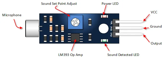
Arduino Sound Detection Sensor Pin Outs
The image and table below detail the controls, pin outs, and other key components for the common 3-pin digital output module.
| Component/Pin | Description |
|---|---|
| VCC | Power Supply: Typically 3.3V to 5V DC. |
| GND | Ground connection. |
| OUT | Digital Output Pin. HIGH when sound is below threshold, LOW when sound exceeds threshold. |
| Power LED | Illuminates when power is applied to the module. |
| Status LED (D0 LED) | Illuminates when sound is detected (i.e., when OUT pin is LOW). |
| Sensitivity Adjust Potentiometer | Adjusts the sound level threshold. Turning Clockwise (CW) generally increases sensitivity (triggers on quieter sounds), Counter-Clockwise (CCW) decreases sensitivity (requires louder sounds to trigger). |
| Microphone | Electret microphone that picks up sound. |
Arduino Sound Detection Sensor Tutorial
Connect the Sound Sensor Module to your Arduino
This is a typical three-pin hook up as shown below:
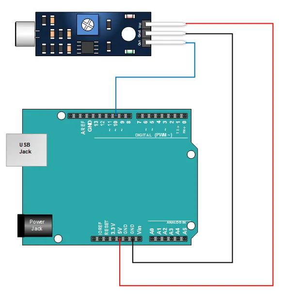
- Module GND to Arduino GND
- Module VCC to Arduino 5V
- Module OUT to Arduino Digital Pin 10 (or any other digital pin)
Copy This Tutorial Sketch and Upload It
This simple sketch reads the digital output of the sound sensor. When the sound level exceeds the threshold set by the potentiometer, the sensor's OUT pin goes LOW. The sketch detects this change and prints a message to the Serial Monitor. It includes a simple debouncing mechanism using timing to avoid printing the "LOUD" message too rapidly.
// Emre's Bench
// Arduino Sound Detection Sensor Module Tutorial (Digital Output)

const int SOUND_SENSOR_PIN = 10; // Digital pin connected to the sensor's OUT pin
const int LED_PIN = 13;          // Onboard LED on Arduino Uno/Nano

int soundSensorState = HIGH;     // Variable to store the current sensor state (HIGH = quiet)
boolean isLoud = false;          // Flag to track if we are currently in a "LOUD" state

unsigned long lastLoudTime = 0;  // Time when the sound was last detected as loud
const long quietInterval = 500;  // Milliseconds to wait after sound stops before printing "quiet"

void setup() {
  Serial.begin(9600);              // Initialize serial communication
  pinMode(SOUND_SENSOR_PIN, INPUT); // Set the sensor pin as input
  pinMode(LED_PIN, OUTPUT);        // Set the onboard LED pin as output
  Serial.println("Sound Sensor Test Started");
}

void loop() {
  // Read the digital state of the sound sensor
  soundSensorState = digitalRead(SOUND_SENSOR_PIN);

  if (soundSensorState == LOW) { // Sound detected (signal is LOW)
    digitalWrite(LED_PIN, HIGH); // Turn on the LED

    // If we weren't already in a loud state, print the message and set the flag
    if (!isLoud) {
      Serial.println("LOUD SOUND DETECTED!");
      isLoud = true;
    }
    lastLoudTime = millis(); // Update the time whenever sound is detected

  } else { // No sound detected (signal is HIGH)
    digitalWrite(LED_PIN, LOW);  // Turn off the LED

    // If we were previously in a loud state AND enough time has passed, print "quiet"
    if (isLoud && (millis() - lastLoudTime > quietInterval)) {
      Serial.println("Quiet");
      isLoud = false; // Reset the flag
    }
  }

  // Small delay to prevent overwhelming the serial port (optional)
  delay(50);
}
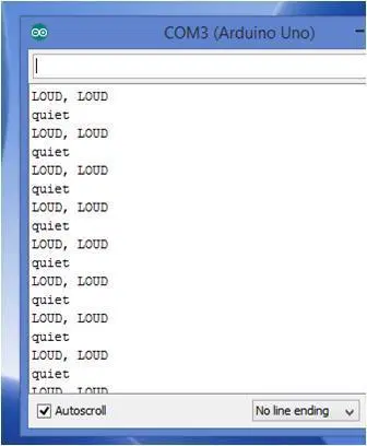
Run The Sketch and Verify Output
Once your sketch is running, open the Serial Monitor (set baud rate to 9600). Adjust the potentiometer on the module: turn it clockwise to make it more sensitive (triggers on quieter sounds) or counter-clockwise to make it less sensitive (requires louder sounds).
Make some loud noises (like clapping) near the microphone. The "Status LED" on the module and the onboard LED (Pin 13) on your Arduino should illuminate when the sound exceeds the threshold. The Serial Monitor should print "LOUD SOUND DETECTED!". When it becomes quiet again for the duration specified by `quietInterval`, it should print "Quiet". Your output should look something like the picture below: