Arduino IR Obstacle Sensor: Tutorial and Manual
Arduino Infrared Obstacle Avoidance
This is yet another one of those modules with cool possibilities. You could for example, sound an alarm when something got too close or you could change the direction of a robot or vehicle.
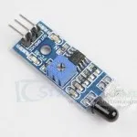
The device consists of an Infrared Transmitter (clear LED) and an Infrared Detector (dark LED), and support circuitry including a comparator (LM393). It only requires three connections to the Arduino. When it detects an obstacle within the set range, it sends its digital output pin LOW.
How to Purchase
There are several different styles of these modules available. If this particular one suits your needs, you can purchase one from the sellers below:
IR Obstacle Detection Module Pin Outs & Controls
The drawing and table below identify the function of module pin outs, controls and indicators.
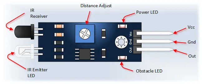
| Pin / Control / Indicator | Description |
|---|---|
| Vcc | 3.3V to 5V DC Supply Input |
| Gnd | Ground Input |
| Out | Digital Output. Goes LOW when an obstacle is detected within range, otherwise HIGH. |
| Power LED | Illuminates when power is applied. |
| Obstacle LED | Illuminates when an obstacle is detected (Output is LOW). |
| Distance Adjust Potentiometer | Adjusts detection distance (typically 2cm to 30cm). Counter-Clockwise (CCW) decreases distance, Clockwise (CW) increases distance. |
| IR Emitter | Infrared emitter LED (often clear). |
| IR Receiver | Infrared receiver/phototransistor (often dark) that receives the reflected signal. |
Arduino IR Obstacle Sensor Module Tutorial
Connect the Arduino to the Detection Module
Use the picture below. It only requires three wires.
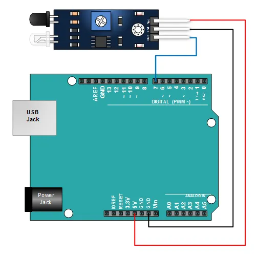
- Module GND to Arduino GND
- Module VCC to Arduino 5V
- Module OUT to Arduino Digital Pin 7
Copy, Paste and Upload the Sample Sketch
// Emre's Bench - IR Obstacle Collision Detection Module Tutorial

const int LED_PIN = 13;          // Arduino Uno onboard LED pin
const int OBSTACLE_PIN = 7;      // Input pin connected to the sensor's OUT pin

int obstacleState = HIGH;        // Variable to store the sensor state (HIGH = clear, LOW = obstacle)

void setup() {
  pinMode(LED_PIN, OUTPUT);      // Set the LED pin as output
  pinMode(OBSTACLE_PIN, INPUT);  // Set the sensor pin as input
  Serial.begin(9600);            // Initialize serial communication
  Serial.println("IR Obstacle Sensor Test");
}

void loop() {
  // Read the state of the obstacle sensor pin
  obstacleState = digitalRead(OBSTACLE_PIN);

  // Check if an obstacle is detected
  if (obstacleState == LOW) {
    Serial.println("OBSTACLE DETECTED!");
    digitalWrite(LED_PIN, HIGH); // Turn on the Arduino LED
  } else {
    Serial.println("Clear");
    digitalWrite(LED_PIN, LOW);  // Turn off the Arduino LED
  }

  delay(200); // Wait a short time before the next reading
}
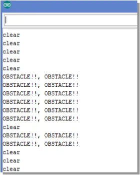
Test the Tutorial Sketch
Move your hand towards the IR LEDs on the module. As your hand enters the detection range (which you can adjust with the potentiometer), the "Obstacle LED" on the module and the onboard LED (Pin 13) on your Arduino should illuminate.
Open the Serial Monitor (set to 9600 baud). You should see "Clear" printed repeatedly. When you move your hand into range, the output should change to "OBSTACLE DETECTED!". The output should look similar to the picture below: