Arduino GY-273 HMC5883L Magnetometer Compass Tutorial
Find Your Heading with an Arduino
Based on the Honeywell HMC5883L, the GY-273 sensor module allows you add an electronic compass to your projects. While coding for the device can be a bit of a chore, there available libraries that make putting it to practical us a snap.
The device communicates with your Arduino via I2C.
This tutorial will show you how to connect the sensor and run sample sketch. It will also point you to a fantastic Adafruit library that will make using the device easy.
Getting a GY-273
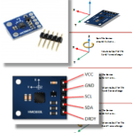
GY-273 Sensor Module Pin-outs
The device has five pins. In most applications (and this tutorial), you will only be concerned with four of them.
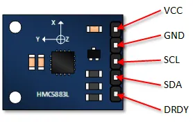
- VCC: Power supply (typically 3.3V or 5V, check module specs).
- GND: Ground connection.
- SCL: I2C Clock line. Connect to Arduino SCL pin (A5 on Uno/Nano, 21 on Mega).
- SDA: I2C Data line. Connect to Arduino SDA pin (A4 on Uno/Nano, 20 on Mega).
- DRDY: Data Ready interrupt pin (often unused in basic examples).
Functional Description
This is a pretty complicated device, that by itself could take pages to describe. This tutorial simply highlights the basics.
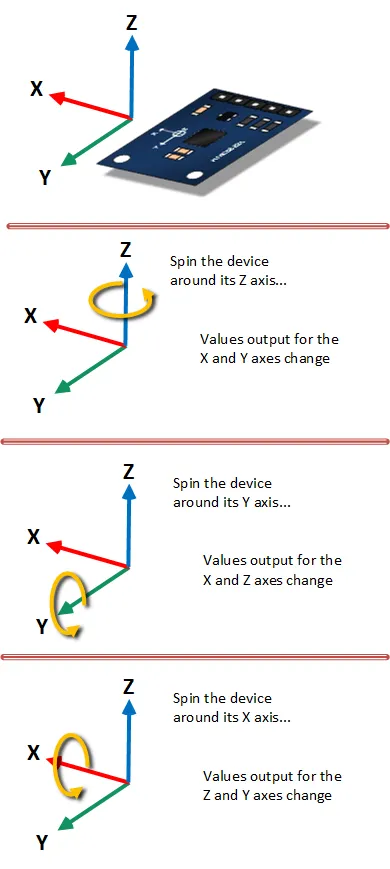
The Honeywell HMC5883L sensor used in the module is sensitive to the earth's magnetic fields in three axes. These axes are labeled as X, Y, and Z. An output is provided for each of these axes that describes the position of these axes relative to the earth’s magnetic field.
As illustrated, twisting or turning the device will provide the corresponding outputs.
GY-273 Arduino Basic Output Tutorial
In this tutorial, you will connect the GY-273, load a basic sketch and see an output to your serial monitor. The purpose of this tutorial is to verify that you can read the raw output.
Connect the Arduino to the GY-273
Just four connections are required. Refer to the picture below. Make sure to connect VCC to the appropriate voltage for your module (often 3.3V or 5V).
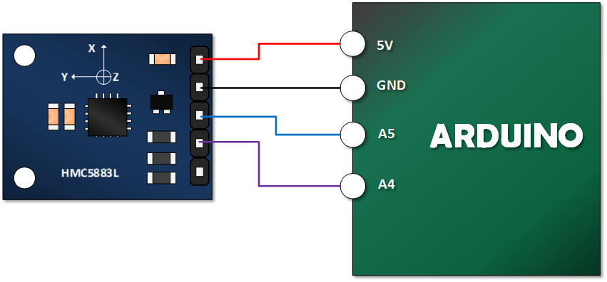
- Module VCC to Arduino 5V (or 3.3V depending on module)
- Module GND to Arduino GND
- Module SCL to Arduino SCL (A5 on Uno/Nano)
- Module SDA to Arduino SDA (A4 on Uno/Nano)
Copy, Paste and Upload the GY-273 Example Sketch
This sketch reads the raw X, Y, and Z axis values directly from the sensor via I2C.
#include <Wire.h> //I2C Arduino Library

#define addr 0x1E //I2C Address for The HMC5883L

void setup(){
  Serial.begin(9600);
  Wire.begin();

  // Put the HMC5883 IC into the correct operating mode
  Wire.beginTransmission(addr); // Start talking
  Wire.write(0x02); // Select Mode register
  Wire.write(0x00); // Set to Continuous measurement mode
  Wire.endTransmission();
}

void loop(){
  int x, y, z; // triple axis data

  // Tell the HMC5883 where to begin reading data
  Wire.beginTransmission(addr);
  Wire.write(0x03); // Select register 3, X MSB register
  Wire.endTransmission();

  // Read the data.. 2 bytes for each axis.. 6 total bytes
  Wire.requestFrom(addr, 6);
  if(Wire.available() >= 6){
    x = Wire.read() << 8; // X axis MSB
    x |= Wire.read();     // X axis LSB
    z = Wire.read() << 8; // Z axis MSB
    z |= Wire.read();     // Z axis LSB
    y = Wire.read() << 8; // Y axis MSB
    y |= Wire.read();     // Y axis LSB
  }

  // Show Values
  Serial.print("X Value: ");
  Serial.println(x);
  Serial.print("Y Value: ");
  Serial.println(y);
  Serial.print("Z Value: ");
  Serial.println(z);
  Serial.println();

  delay(500); // Wait half a second
}
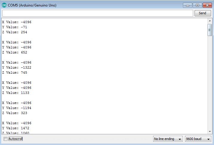
Open the Serial Monitor and Verify Your Output.
Set your Serial Monitor to 9600 baud. Your output should look something like this. Once you’ve established that you have an output, try turning your device along its various axes and view the results.
Run the Adafruit Example
Using a library simplifies interacting with the sensor and calculating the heading. Adafruit provides excellent libraries for this.
You won’t need to change any of your wiring connections.
Get the Libraries
You will need two libraries from Adafruit:
- Adafruit Unified Sensor Driver: This is a base library required by many Adafruit sensor libraries. Download from GitHub or install via the Arduino Library Manager (search for "Adafruit Unified Sensor").
- Adafruit HMC5883 Unified Driver: This library specifically handles the HMC5883L sensor. Download from GitHub or install via the Arduino Library Manager (search for "Adafruit HMC5883 Unified").
If you download manually, make sure to install the libraries correctly in your Arduino `libraries` folder.
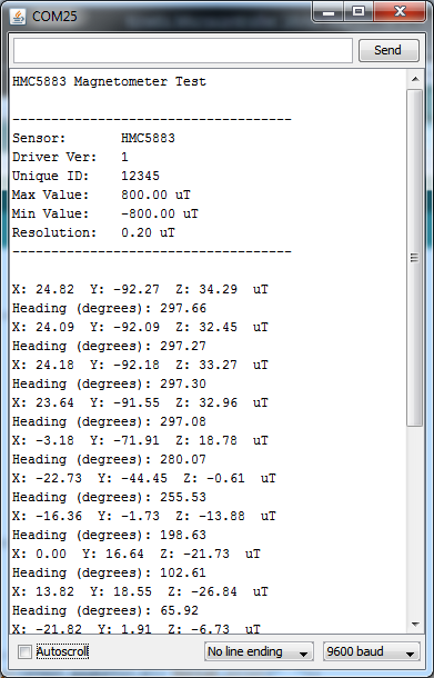
Run Adafruit’s HMC5883L Example
Navigate to the Examples directory under your Arduino IDE file menu (File -> Examples). Under "Adafruit HMC5883 Unified", you should find an example sketch (often named `hmc5883` or similar). Open it, upload it and open your serial monitor (usually at 9600 baud).
When the plane defined by the X and Y axes of the sensor is parallel to the ground, the example sketch will calculate and output the compass heading in degrees.
Note: Magnetometers are sensitive to nearby magnetic fields (motors, metal objects). For accurate readings, keep the sensor away from such interference. Calibration might also be necessary for precise results, which is often covered in more advanced examples or the library documentation.