OH137 Arduino Hall Effect Switch Tutorial
Introduction: The Unipolar Hall Switch
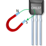
This device is referred to as a Unipolar Hall Effect Magnetic Switch. In a magnet, magnetic lines of flux flow from the north pole to the south pole.
If the magnetic flux lines from a magnet's south pole pass through the *front face* of the OH137 sensor with sufficient strength (magnetic flux density), the sensor's output pin will be pulled LOW.
These sensors are often used for applications like speed detection (e.g., counting rotations with magnets attached to a wheel) or proximity detection (e.g., detecting if a lid with a magnet is closed).
Where to buy these switches
These switches are available on both Amazon and eBay.
OH137 Hall Switch Pin Outs and Specifications
This device requires power and ground. When in the presence of a sufficiently strong magnetic south pole field perpendicular to its face, the output pin goes LOW.
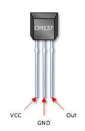
- VCC: Power supply input, typically 4.5V to 24V DC (check your specific datasheet, but 5V from Arduino works).
- GND: Circuit common or ground.
- OUT: Digital Output. This pin is normally HIGH (due to an internal or external pull-up resistor) and goes LOW when a sufficient south pole magnetic field is detected. It can typically sink up to 25mA.
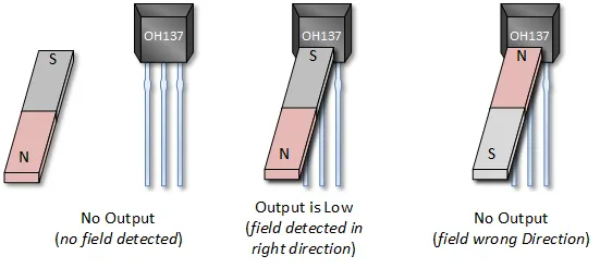
OH137 and the Magnetic Field Direction
As previously discussed, the OH137 is a unipolar device. This means the magnetic field must be of sufficient strength and must be oriented correctly (south pole facing the front/branded face of the sensor) to trigger the output low. The image below illustrates this requirement.
OH137 Hall Switch with an Arduino Tutorial
Connect Your Arduino to the OH137
The OH137 has an open-collector output, meaning it pulls the OUT pin LOW when activated but doesn't actively drive it HIGH. Therefore, you need an external pull-up resistor connected between the OUT pin and VCC (5V). The capacitor is optional but recommended for filtering noise.
You will need:
- OH137 Hall Effect Sensor
- 10kΩ Resistor (Pull-up resistor - value can often range from 4.7kΩ to 10kΩ)
- 0.1µF Capacitor (100nF or '104' marking - Optional filter, connect between OUT and GND)
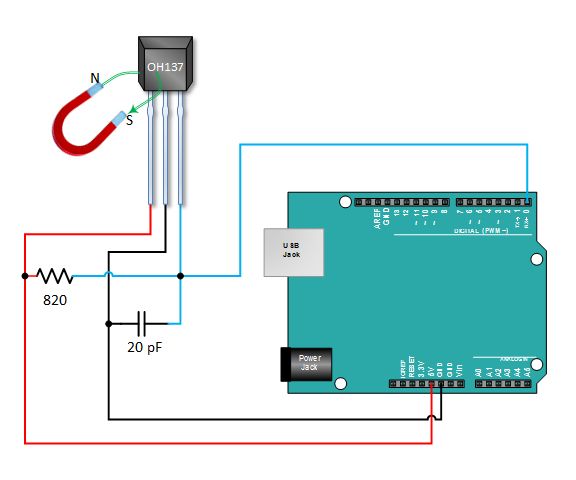
- OH137 Pin 1 (VCC) to Arduino 5V
- OH137 Pin 2 (GND) to Arduino GND
- OH137 Pin 3 (OUT) to Arduino Digital Pin 2 (or any digital pin)
- 10kΩ Resistor between OH137 Pin 3 (OUT) and Arduino 5V
- (Optional) 0.1µF Capacitor between OH137 Pin 3 (OUT) and Arduino GND
Copy Paste and Upload the OH137 Tutorial Sketch
This sketch reads the digital state of the Hall effect sensor and prints a message to the Serial Monitor when a magnetic field is detected or removed.
// Emre's Bench
// OH137 Hall Effect Sensor Tutorial

const int hallPin = 2;     // Digital pin connected to the OH137 OUT pin
const int ledPin = 13;     // Onboard LED on Arduino Uno/Nano

int hallState = HIGH;      // Variable to store the sensor state (HIGH = no field)
boolean fieldPresent = false; // Flag to track if a field is currently detected

void setup() {
  Serial.begin(9600);
  pinMode(hallPin, INPUT);    // Set hallPin as input (pull-up is external)
  pinMode(ledPin, OUTPUT);    // Set onboard LED as output
  digitalWrite(ledPin, LOW); // Ensure LED is off initially
  Serial.println("OH137 Hall Effect Sensor Test");
  Serial.println("Bring South Pole of magnet near sensor face...");
}

void loop() {
  // Read the state of the Hall effect sensor
  hallState = digitalRead(hallPin);

  if (hallState == LOW) { // LOW means magnetic field detected
    digitalWrite(ledPin, HIGH); // Turn on LED

    // Print message only once when the field is first detected
    if (!fieldPresent) {
      Serial.println("MAGNETIC SOUTH POLE DETECTED");
      fieldPresent = true;
    }
  } else { // HIGH means no magnetic field detected
    digitalWrite(ledPin, LOW); // Turn off LED

    // Print message only once when the field is first removed
    if (fieldPresent) {
      Serial.println("No magnetic field detected");
      fieldPresent = false;
    }
  }

  // Small delay to prevent spamming the serial monitor too quickly
  delay(100);
}
Verify That the OH137 Works
Open your Arduino IDE Serial Monitor (set to 9600 baud). Now move the **south pole** of a magnet close to the **front face** (the side with the writing/bevel) of the OH137 sensor. If the magnetic field is strong enough and correctly oriented, the Arduino's onboard LED (pin 13) should turn ON, and the Serial Monitor will print "MAGNETIC SOUTH POLE DETECTED". When you remove the magnet, the LED should turn OFF, and the monitor should print "No magnetic field detected".