Arduino PS2 Joystick Tutorial (KY-023 / Deek Robot)
A Versatile Input Device
The PS2 style joystick is a thumb-operated device that, when put to creative use, offers a convenient way of getting operator input. It fundamentally consists of two potentiometers (for X and Y axes) and a push-button switch (activated by pressing down on the joystick).
The two potentiometers indicate the direction and extent the joystick is being pushed along the X and Y axes.
The switch sends a LOW signal (Ground) when the joystick knob is pressed down.
Finding a PS2 Joystick
There are a few slightly different varieties offered, but that all operate pretty much the same.
Arduino PS2 Joystick Pin Outs
This input device interfaces to your Arduino via five pins. Three provide input signals to the Arduino (X-axis, Y-axis, Switch), while the remaining two supply voltage and ground.
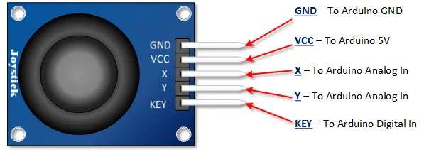
- GND: Ground connection.
- +5V: Connects to 5V power supply from the Arduino.
- VRx: Analog output for the X-axis potentiometer (0-5V).
- VRy: Analog output for the Y-axis potentiometer (0-5V).
- SW: Digital output for the push button switch. Goes LOW when pressed, normally HIGH (requires external or internal pull-up).
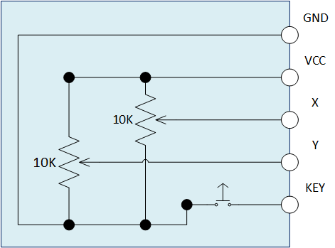
Arduino PS2 Joystick Schematic
As shown in the schematic, the joystick uses two potentiometers connected as voltage dividers. Full deflection in either direction on an axis will provide approximately Ground (0V) or the supply voltage (5V) at the corresponding VRx or VRy output pin. The SW pin connects to ground through the push button when pressed.
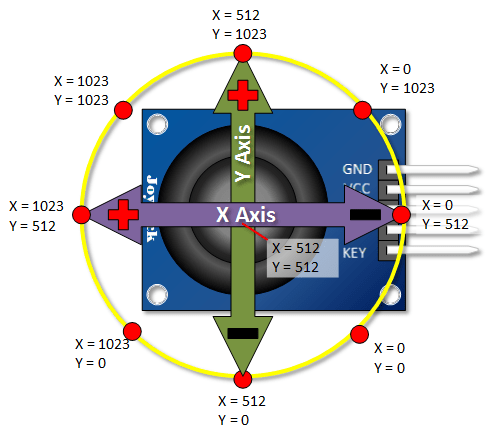
Arduino PS2 Joystick Output Orientation
To use this thumb control effectively, you need to understand which physical direction corresponds to the X and Y axes and how the analog output values change.
This tutorial uses Arduino's `analogRead()`, which returns values between 0 and 1023 (for a 10-bit ADC and 5V reference).
The graphic below shows the typical X and Y directions and how the analog outputs respond when the joystick is pushed. The center (resting) position should ideally read around 512 for both axes.
Note: This graphic is based on the common Deek-Robot/Keyes module. Your specific module might have slightly different resting values or orientations. Experimentation is key!
Arduino PS2 Joystick Tutorial
Assemble the PS2 Joystick Project
Connect the joystick module to your Arduino as shown. Note the use of an external 10kΩ pull-up resistor for the switch (SW) pin, connecting it to 5V. While you could use the Arduino's internal pull-up (`pinMode(KEYin, INPUT_PULLUP);`), using an external one is shown here.
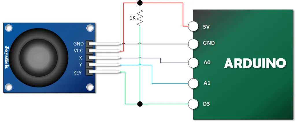
- Module GND to Arduino GND
- Module +5V to Arduino 5V
- Module VRx to Arduino Analog Pin A0
- Module VRy to Arduino Analog Pin A1
- Module SW to Arduino Digital Pin 3
- 10kΩ Resistor between Arduino Digital Pin 3 and Arduino 5V (External Pull-up)
Load Your PS2 Tutorial Sketch
Copy and paste the following sketch into your Arduino IDE and upload it to your board.
// Emre's Bench
// Arduino PS2 Joystick Module Tutorial (KY-023 / Deek-Robot)

const int VRx_PIN = A0; // Arduino pin connected to VRx
const int VRy_PIN = A1; // Arduino pin connected to VRy
const int SW_PIN = 3;   // Arduino pin connected to SW

void setup() {
  Serial.begin(9600);       // Initialize serial communication
  pinMode(SW_PIN, INPUT);   // Set SW pin as input
  // Note: An external pull-up resistor is used in the wiring diagram.
  // If not using an external pull-up, enable the internal one:
  // pinMode(SW_PIN, INPUT_PULLUP);
}

void loop() {
  int xVal, yVal, buttonVal;

  // Read the analog values from the potentiometers
  xVal = analogRead(VRx_PIN);
  yVal = analogRead(VRy_PIN);

  // Read the digital state of the push button
  buttonVal = digitalRead(SW_PIN);

  // Print the values to the Serial Monitor
  Serial.print("X = ");
  Serial.print(xVal); // Print raw ADC value (0-1023)

  Serial.print("\t Y = ");
  Serial.print(yVal); // Print raw ADC value (0-1023)

  Serial.print("\t Button: ");
  if (buttonVal == HIGH) { // HIGH means not pressed (due to pull-up)
    Serial.println("Not Pressed");
  } else {                 // LOW means pressed
    Serial.println("PRESSED");
  }

  delay(500); // Wait half a second before the next reading
}
Open the Serial Monitor (set to 9600 baud). Move the joystick around and press the button. You should see the X and Y values change (ideally ranging from near 0 to near 1023, with the center around 512), and the button status should change when pressed.