Arduino MAX471 Current Sensor Module Tutorial
Use the MAX471 to Measure Current on the High Side
The MAX471 is a solid alternative to an ACS712 for measuring DC Current. It's a high side device that is powered by a load source that can range anywhere from 3 to 36 VDC. That said, a key benefit is its scale factor as it outputs 1 volt per amp measured (up to 3A).
This tutorial will walk you through some of the basics necessary to put this device to use.
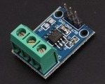
There are a few varieties available, but they are basically the same.
Getting a Max471
The MAX471 is available from these online locations
MAX471 Current Sensor Module Pin Outs
There are five pins of interest for this device. The image below identifies them.
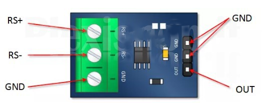
RS+: This connects to the positive pole of your supply source.
RS-: This connects to the high side of your load.
GND: This is circuit common on both the input and the output side.
OUT: This is an analog output that provide 1 volt DC per amp measured. The device can measure up to 3 amps DC.
(Note: Some MAX471 modules also include voltage measurement pins (VT, VOUT, VIN). This tutorial focuses on the current-only version.)
How the MAX471 is Installed in the Circuit
As a high side current sensor, positioning is important, especially since the chip gets its power from the load’s source.
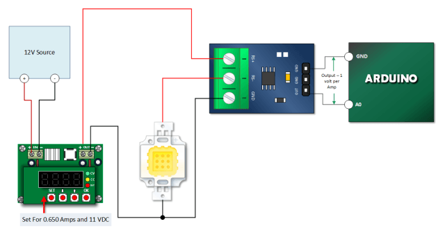
The picture below is intended to help you to visualize that requirement.
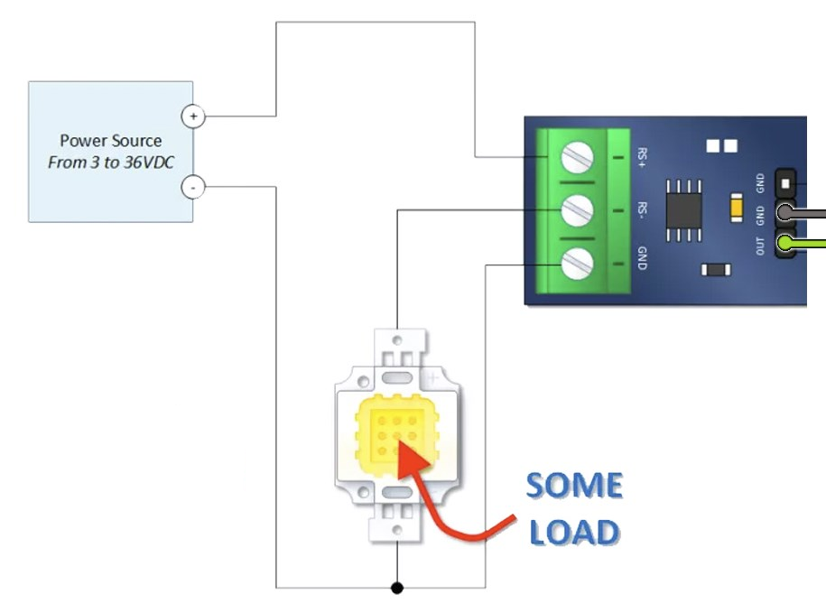
Notice how the power supply positive terminal is connected to RS+. Also notice how RS- is connected to the positive side of the load. Finally, take a gander a the module ground connection. It is connected to the negative side of the power source.
Arduino MAX471 Current Sensor Module Arduino Tutorial
Make the Tutorial Connections
Connect your Arduino, MAX471, power source, and load as shown below. I’m using my trusty Minghe B3603 power supply to drive a 10W LED. I like the B3603 because I can monitor the relative validity of the results seen on my serial monitor. The 10W LED works well for this tutorial.
Copy, Paste and Upload the MAX471 Arduino Sketch
The sketch is nothing more than a Simple Arduino Voltmeter that has been modified for this device. At a scale factor of 1V per Amp, it is very convenient.
/*
 Emre's Bench
 MAX471 Current Sensor Tutorial
 Reads the analog output from the MAX471 and converts it to Amps.
*/

const int max471In = A0; // Analog pin connected to the MAX471 OUT pin

int RawValue= 0;        // Variable to store the raw ADC value
float Voltage = 0;      // Variable to store the voltage read from MAX471 OUT pin
float Current = 0;      // Variable to store the calculated current in Amps

void setup() {
  // Initialize the serial communication
  Serial.begin(9600);
  // No need to set pinMode for analog input explicitly, but good practice:
  pinMode(max471In, INPUT);
}

void loop() {
  // Read the raw analog value from the sensor
  RawValue = analogRead(max471In);

  // Convert the raw ADC value to voltage (0-5V range, 1024 steps)
  // Voltage = (Raw ADC Value / ADC Resolution) * Reference Voltage
  Voltage = (RawValue * 5.0) / 1024.0; // Using 5.0V as reference

  // Convert the voltage reading to current using the MAX471's scale factor (1V/A)
  // Since the scale is 1V/A, the voltage reading directly equals the current in Amps.
  Current = Voltage;

  // Print the results to the Serial Monitor
  Serial.print("Raw ADC: ");
  Serial.print(RawValue);
  Serial.print("\t Voltage Out: ");
  Serial.print(Voltage, 3); // Print voltage with 3 decimal places
  Serial.print(" V");
  Serial.print("\t Current: ");
  Serial.print(Current, 3); // Print current with 3 decimal places
  Serial.println(" A");

  // Wait for 1.5 seconds before the next reading
  delay(1500);
}
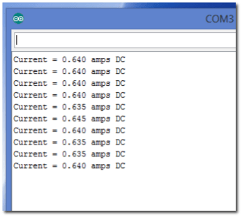
Verify Your Tutorial Results
Open your serial monitor and verify your results. If you’re successful, you should see current readings that are close to what you expected based on your load.