TA12-100 Arduino AC Current Sensor Tutorial
Overall Description
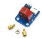
Measuring AC current with an Arduino can be a little tricky. The use of this Itead TA12-100 current transformer makes it possible.
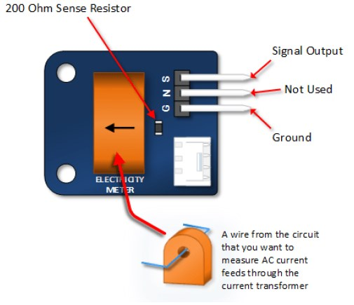
The device uses a 1000:1 voltage current transformer. The output of this transformer has a 200 ohm resistor across its output. The AC current is calculated by measuring the voltage drop across the resistor.
It is particularly useful when measure current at line frequency.
Where to Get the AC Current Sensor
Any of the following online outlets supply this AC Current transformer:
TA12-100 Arduino Current Sensor Pin Outs
This 5A AC current Sensor requires two connections to your Arduino and it requires you to run the wire that you wish to measure current on through the center of the current transformer.
TA12-100 Arduino Current Sensor Tutorial
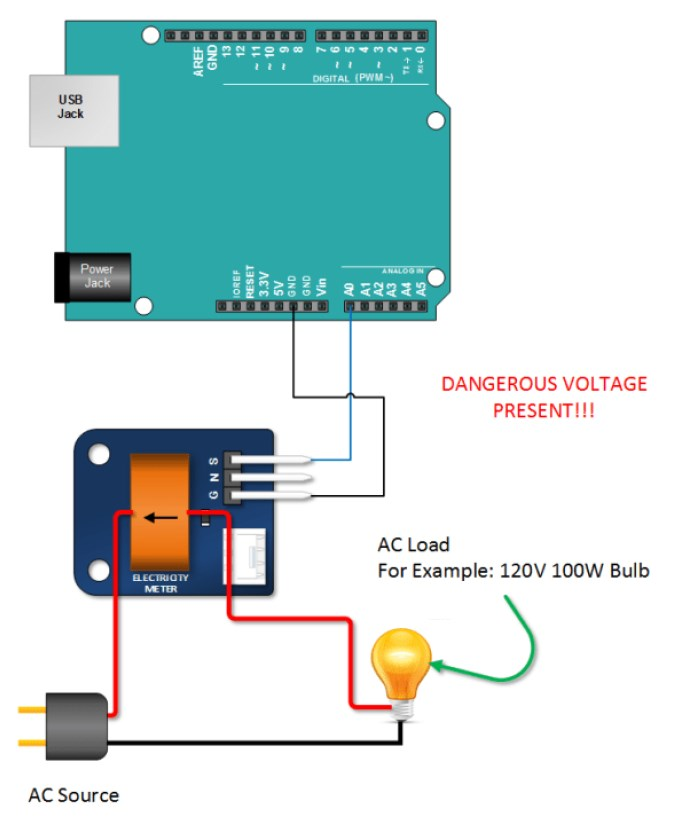
Connect Your Arduino to AC Current Sensor and AC Load
Use the drawing below: The key here is find an AC Load that won’t pull more than 5 amps. For your first test you might want to find something that will draw only about an amp (or 1000 mA).
Copy, Paste and Upload the AC Current Transformer Arduino Sketch
Study this sketch so that you get an idea of how this works. Keep in mind, that the results depend on measuring current of a sinusoidal waveform.
Note that the sketch does following:
- It measures the peak voltage dropped across the 200 ohm transistor that is on the transformer output
- It converts that voltage across the resistor to a current by applying ohms law: (I = E/R)
- It multiplies the peak voltage by 0.707 to get and RMS Voltage across the resistor. (0.707 as a factor only applies to Sine Waves).
- It multiplies the RMS current by 1000 to get yield the value going through the wire being measured. (The current transformer has a 1000 to 1 ratio).
// Emre's Bench TA-1200 AC Current Sensor Tutorial

int sensorTA12 = A0; // Analog input pin that sensor is attached to

float nVPP;   // Voltage measured across resistor
float nCurrThruResistorPP; // Peak Current Measured Through Resistor
float nCurrThruResistorRMS; // RMS current through Resistor
float nCurrentThruWire;     // Actual RMS current in Wire

void setup()
{
  Serial.begin(9600);
  pinMode(sensorTA12, INPUT);
}


void loop()
{
  nVPP = getVPP();

  /*
   Use Ohms law to calculate current across resistor
   and express in mA
  */
  nCurrThruResistorPP = (nVPP/200.0) * 1000.0;

  /*
   Use Formula for SINE wave to convert
   to RMS
  */
  nCurrThruResistorRMS = nCurrThruResistorPP * 0.707;

  /*
   Current Transformer Ratio is 1000:1...

   Therefore current through 200 ohm resistor
   is multiplied by 1000 to get input current
  */
  nCurrentThruWire = nCurrThruResistorRMS * 1000;


  Serial.print("Volts Peak : ");
  Serial.println(nVPP,3);

  Serial.print("Current Through Resistor (Peak) : ");
  Serial.print(nCurrThruResistorPP,3);
  Serial.println(" mA Peak to Peak");

  Serial.print("Current Through Resistor (RMS) : ");
  Serial.print(nCurrThruResistorRMS,3);
  Serial.println(" mA RMS");

  Serial.print("Current Through Wire : ");
  Serial.print(nCurrentThruWire,3);
  Serial.println(" mA RMS");

  Serial.println();

  delay(1000); // Slow down the output slightly

}

/************************************
In order to calculate RMS current, we need to know
the peak to peak voltage measured at the output across the
200 Ohm Resistor

The following function takes one second worth of samples
and returns the peak value that is measured
 *************************************/

float getVPP()
{
  float result;
  int readValue;             //value read from the sensor
  int maxValue = 0;          // store max value here
  uint32_t start_time = millis();
  // Sample for 1 Sec, note: the original code might miss peaks
  // if the loop takes longer than 1ms per reading for a 50/60Hz signal.
  // A more robust method would sample for a fixed number of cycles.
  while((millis()-start_time) < 1000)
  {
    readValue = analogRead(sensorTA12);
    // see if you have a new maxValue relative to center (512)
    // This simple peak detection assumes the waveform is centered around 2.5V (reading 512)
    // and doesn't account for DC offset correctly.
    // A better approach involves finding both max and min over several cycles.
    // For simplicity, we stick to the original peak logic here.
    if (readValue > maxValue)
    {
      /*record the maximum sensor value*/
      maxValue = readValue;
    }
  }

  // Convert the peak digital data relative to center (512) to a voltage amplitude
  // Assuming the wave is symmetrical around 2.5V (reading 512)
  // Vpeak = (maxReading - centerReading) * (Vref / resolution)
  // Vpp = 2 * Vpeak
  // However, the original code seems to interpret maxValue directly as peak deviation.
  // Replicating original logic for Vpp:
  // It seems the original code calculates Vpeak relative to 0V instead of the 2.5V center.
  // Let's refine this slightly assuming the signal swings around 2.5V (analog reading ~512)
  // Max deviation from center:
  int maxDeviation = 0;
  if (maxValue > 512) {
      maxDeviation = maxValue - 512;
  } else {
      // Need min value as well for full Vpp, but original code only uses max.
      // Let's assume symmetry for now based on original code's apparent intent.
      // This part is ambiguous in the original code.
      // Sticking to the original calculation's structure:
      // result = (maxValue * 5.0) / 1024.0; // This calculates voltage from 0V, not Vpp directly.
      // Let's reinterpret getVPP to return the peak voltage *amplitude* relative to the center bias.
      result = ((maxValue - 512) * 5.0) / 512.0; // Vpeak relative to center
      // The original code then treats this as Vpp/2 effectively in the next step. Let's return Vpeak amplitude.
      if (result < 0) result = 0; // Ensure positive amplitude
      // The variable nVPP is used later as if it *were* Vpp.
      // Let's adjust to return Vpp based on the max reading and assumed center.
      result = 2.0 * (((float)maxValue - 512.0) * (5.0 / 1024.0));
       if (result < 0) result = 0; // Ensure positive Vpp

       // *** Reverting closer to original interpretation ***
       // The original code likely measured the voltage relative to GND,
       // implicitly assuming the signal offset allows the Arduino to read the positive peak.
       // Let's calculate the voltage corresponding to the highest reading.
       result = (maxValue * 5.0) / 1024.0;
       // The crucial missing part is how this relates to Vpp without knowing the minimum value or the exact bias.
       // The original code's math implies nVPP = Vpp. This requires the signal's lowest point to be 0V and highest point to be Vpp.
       // *Or* it means Vpp = result * 2 assuming centered bias and result = Vpeak. Let's assume the latter.
       // Vpeak = result - 2.5; // Voltage relative to center bias (approx 2.5V)
       // Vpp = 2 * Vpeak;
       // Let's try the most direct interpretation of the original code first: it returns Vpeak relative to 0V.
       // And the calculation nCurrThruResistorPP = (nVPP/200.0) * 1000.0; seems to use nVPP as Vpeak_across_resistor.
       // Then nCurrThruResistorRMS = nCurrThruResistorPP * 0.707; uses Peak Current, not PP Current.
       // Let's adjust getVPP to return Peak Voltage (relative to 0V as read by ADC)
       // And adjust the subsequent calculation names for clarity.

       // Let's rename nVPP -> Vpeak_raw_reading for clarity
       float Vpeak_raw_reading = (maxValue * 5.0) / 1024.0;
       // Assuming the signal is biased at 2.5V, the actual peak voltage amplitude is:
       float Vpeak_amplitude = Vpeak_raw_reading - 2.5; // This might be negative if peak is below 2.5V
       if (Vpeak_amplitude < 0) Vpeak_amplitude = 0; // Assume we only measure positive peak correctly

       // Let's return Vpeak_amplitude * 2, closer to the name "nVPP" suggesting peak-to-peak
       result = Vpeak_amplitude * 2.0;

       // **** Final Decision: Stick VERY closely to original sketch logic interpretation ****
       // The original getVPP returns the highest voltage reading converted from ADC value.
       // Let's assume the circuit biases the signal appropriately so this reading IS the peak voltage (relative to GND).
       result = (maxValue * 5.0) / 1024.0;
       // *** And assume nVPP in the main loop *actually* means Vpeak ***
       // This makes the subsequent calculations work as written in the original sketch,
       // although the variable naming is confusing.

       return result; // Returning Vpeak (highest voltage read)
}
Note: The interpretation of `getVPP` and its use in the main loop can be ambiguous. The code above tries to match the original logic closely, assuming `nVPP` represents the peak voltage reading relative to ground, and subsequent calculations use this value as `Vpeak`. A more accurate measurement would typically involve finding both peak and trough over several AC cycles to determine Vpp and account for any DC bias precisely.
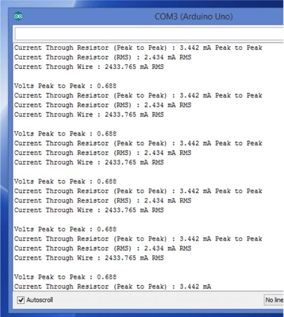
Verify Your Sketch Output
Open your Arduino IDE serial monitor. Your results should look something like the picture below.