MAX6675 Temp Module Arduino Manual and Tutorial
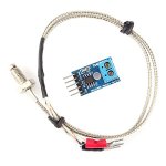
Introducing the MAX6675 for your Arduino
Thermocouples have been around forever and are a great way to measure temperature. They have a very large range, are robust and come in all kinds of lengths, varying tip configurations and a variety sheaths.
The challenge with using thermocouples is with the need for what is known as cold junction compensation and the need to detect a very small voltage change for every degree in change of temperature.
Fortunately there are chips like the MAX6675 that make connecting a thermocouple to your Arduino an affordable breeze. The device measures the output of a K-Type Thermocouple and provides the result to the Arduino via a SPI interface.
Basic Specifications
As you can see in the table below, the fundamental requirements and capabilities jive nicely with the abilities of your Arduino micro-controller.
A word of warning – There are some that sell this module that think it's measurement range is from -200 to 1300 degrees C. They're wrong. The MAX6675 chip measurement range is limited to what is detailed below:
| Specification | Value |
|---|---|
| Supply Voltage | 3.0 to 5.5 VDC |
| Operating Current | about 50mA |
| Measurement Range | 0°C to 1024°C (32°F to 1875°F) |
| Measurement Resolution | 0.25°C (0.45°F) |
| Output | SPI Interface |
| Required Sensor | K-Type Thermocouple |
Temperature Range Note:
It is true that MAX6675 chip will read from 0°C to 1024°C. However, there is another limiting factor: the K-type thermocouple itself, including its insulated wires and cable sheathing. These components also have temperature limits.
It is not unusual for the sheathing on your specific thermocouple to have a maximum temperature *below* the range of the MAX6675 chip. Always check the specifications of your particular thermocouple probe to avoid damage.
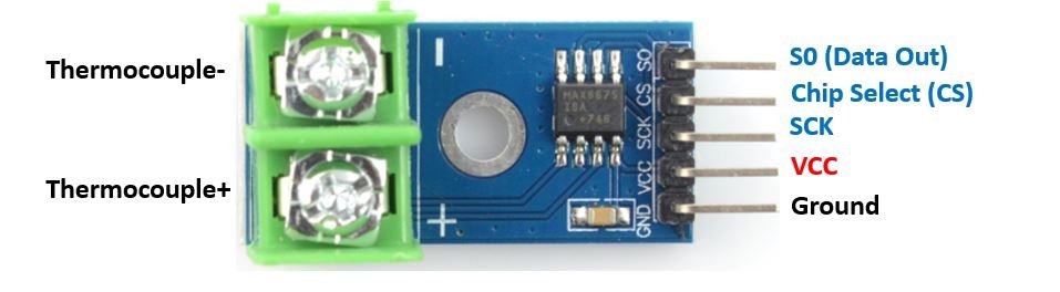
MAX6675 Module Pin Outs
The pin-outs for this module are shown in the illustration below.
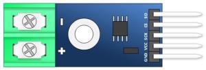
These pins function as follows:
- SO: Serial Out. The module's data output line (MISO). Your Arduino will read this output.
- CS: Chip Select. Setting this pin LOW selects the module and enables communication.
- SCK: Serial Clock. The clock signal input from your Arduino (SPI Clock).
- VCC: Power Supply (typically 3.3V or 5V, matching your Arduino logic level).
- GND: Ground.
- - (Minus): The K-Type thermocouple negative input (usually the red wire).
- + (Plus): The K-Type Thermocouple positive input (usually the yellow wire).
Important Note on Thermocouple Polarity:
Most K-type thermocouples come with a red lead and a yellow lead. The industry standard is typically Red = Negative (-) and Yellow = Positive (+).
However, some suppliers (especially with low-cost modules) might provide thermocouples with reversed colors or incorrectly marked terminals on the module. If you increase the temperature at the thermocouple tip and the reading goes *down*, your connections are likely reversed. Swap the thermocouple wires on the module's screw terminals.
MAX6675 Arduino Thermocouple Module Schematic
This module typically uses the example circuit provided in the official MAX6675 datasheet. In fact, if you were so inclined, you could buy the MAX6675 chip and build your own thermocouple measuring circuit for potentially a few bucks less.
MAX6675 Arduino Tutorial
Get the MAX6675 Arduino Library
Using a library greatly simplifies communication with the MAX6675 via SPI. Adafruit provides a popular and easy-to-use library.
- In the Arduino IDE, go to Sketch > Include Library > Manage Libraries...
- Search for "MAX6675".
- Find the "MAX6675 library by Adafruit" and click "Install".
Alternatively, you can download it directly from GitHub: Adafruit MAX6675 Library on GitHub.
If you download manually, you'll need to install the library. You can read the official Arduino guide on installing libraries if you're unfamiliar.
Connect your Arduino to the Thermocouple Module
Connect the components as shown below. Remember the note about thermocouple polarity when connecting the probe to the screw terminals.
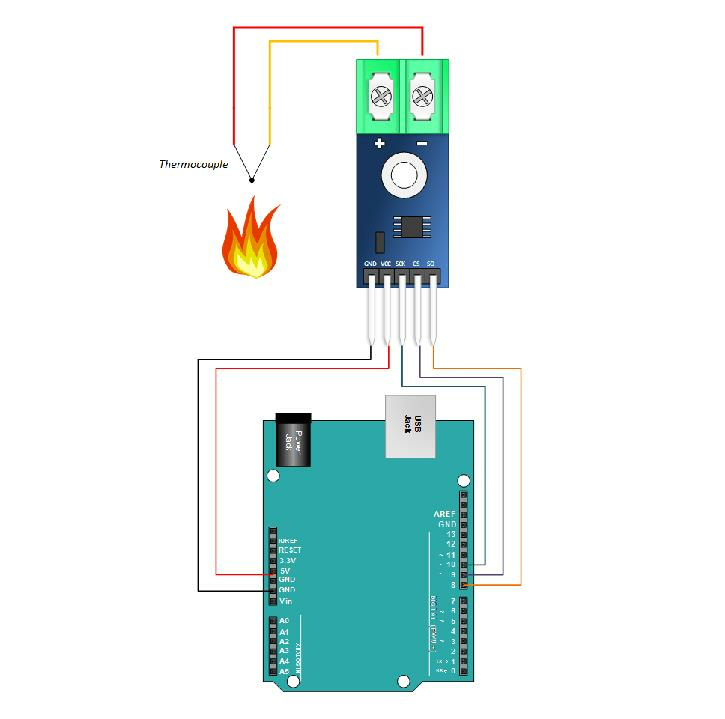
- Module GND to Arduino GND
- Module VCC to Arduino 5V
- Module SCK to Arduino Digital Pin 10 (or your chosen SCK pin)
- Module CS to Arduino Digital Pin 9 (or your chosen CS pin)
- Module SO to Arduino Digital Pin 8 (or your chosen MISO pin)
- Connect the K-Type thermocouple wires to the module's screw terminals (Yellow to +, Red to -).
Copy and Paste the Arduino MAX6675 Sketch
This sketch uses the Adafruit library to read the temperature and display it on the Serial Monitor.
// Emre's Bench - Arduino MAX6675 Tutorial Sketch
// Uses the Adafruit MAX6675 Library

#include "max6675.h" // Include the library

// Define the Arduino pins connected to the MAX6675 module
int ktcSO = 8;  // Serial Out (SO) -> Arduino Digital Pin 8 (MISO)
int ktcCS = 9;  // Chip Select (CS) -> Arduino Digital Pin 9
int ktcCLK = 10; // Serial Clock (SCK) -> Arduino Digital Pin 10

// Initialize the MAX6675 library with the defined pins
MAX6675 ktc(ktcCLK, ktcCS, ktcSO);

void setup() {
  Serial.begin(9600); // Start serial communication
  Serial.println("MAX6675 Test");

  // Give the MAX6675 a little time to stabilize after power-up.
  delay(500);
}

void loop() {
  // Read the temperature from the thermocouple
  double tempC = ktc.readCelsius();
  double tempF = ktc.readFahrenheit();

  // Check if the reading is valid (the library returns NaN for errors)
  if (isnan(tempC)) {
    Serial.println("Error reading thermocouple!");
  } else {
    // Print the temperatures to the Serial Monitor
    Serial.print("Temp C = ");
    Serial.print(tempC);
    Serial.print("\t Temp F = ");
    Serial.println(tempF);
  }

  // Wait 0.5 seconds before the next reading
  // The MAX6675 takes about 0.22 seconds per conversion.
  delay(500);
}
Related Documents
Note: Connecting multiple MAX6675 modules to a single Arduino is possible by sharing the SCK and SO lines but using a unique CS pin for each module. You would then create separate MAX6675 objects in your code, each initialized with its corresponding CS pin.