Arduino ADS1115 Module Getting Started Tutorial
Introducing A Low Cost and Precise Arduino Measurement
The ADS1115 is a 16 bit Analog Digital Converter that can greatly improve your Arduino resolution and measurement accuracy. It has four input channels that can be configured for Single Ended, Differential or Comparator Measurements.
This Tutorial will focus on showing you how to make your first single ended 16 bit measurement with the ADS1115. Even this mode provides a substantial improvement in resolution over your Arduino Analog input.
Other tutorials will demonstrate other powerful features.
See how to make a differential measurement using your ADS1115. This type of measurement allows you to make negative voltage measurements as well.
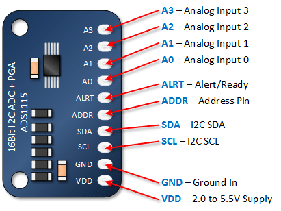
Arduino ADS1115 16 Bit ADC Module Pin Outs
The module below is the most common. It will require addressing ( see the next section ). There are four addresses available.
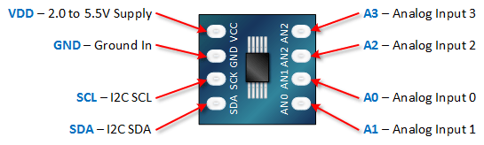
This next module is less common. The address is preset to 0x48. It also does not include the Alert/Ready signal. In most applications, you will not require this signal.
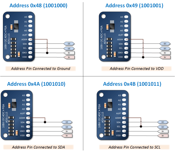
Arduino ADS1115 16 Bit ADC Module Addressing
The four addresses for the ADS1115 are set by connecting the ADDR pin to SCL, SDA, GND or VDD. The image below illustrates how these connections are make and provides the address number for those connections.
Understanding the ADS1115 Resolution
Is it 15 or 16 bits?
The output of the ADS1115 is what as known as a signed integer. That means one of the bits in the 16 bit words is going to be used to tell us if it’s a positive or negative value being reported. This will be discussed more later, but what is important to grasp is that only 15 of the 16 bits are used to communicate the value of the voltage measurement.
What this means is that there are 32,768 possible output values, where zero is the first and 32,767 is the last.
Bottom line is that is indeed a 16 bit device, but only 15 of those bits are use to communicate the magnitude of the measurement.
ADS1115 Full Scale and the Value of Bit
The value of a bit is determined by the Programmable Gain Amplifier (PGA) setting as is this setting establishes full scale. This differs from the Arduino where full scale is determined by a reference voltage. (The PGA will be discussed in another article).
In the default mode, the setting is +/-6.144 volts.
Thus the value of 32767 would represent a value of 6.144 volts.
Dividing 6.144 volts by 32767 yields a scale factor of 0.1875 mV per bit. This is a significant improvement over the Arduino ADC which resolution of approximately 5 mV per bit. In fact, its about 26 times better!
The neat thing about this is that this is worst case. In another PGA setting, you can establish a full scale of +/- 2.048 volts. That provides us a resolution of 0.0635 mV.
ADS1115 Maximum Measurement Range
The PGA setting of +/- 6.144 range can be a little misleading as it seems to infer that you can measure voltages that high. You can’t.
Instead, the maximum measurable voltage is established by the supply voltage to the chip. Specifically, the maximum measurable voltage is 0.3 volts more than the supply voltage. In fact, exceeding this voltage at your analog input may damage your chip.
Note the differentiation here between the PGA range and the maximum measurable voltage. The programmed range determines the value of a bit (or scale factor), while the maximum measurable range determines what your analog input can safely handle.
Arduino ADS1115 Analog to Digital Converter Simple Tutorial
This is a simple tutorial because all you’re going to do is make a simple measurement while observing the resolution and repeat-ability (or precision) of the measurement.
In running this tutorial, we’re going to make use of a library distributed by Adafruit.
Download and Install the Adafruit ADS1X15 Library
As previously mentioned, you will need the Adafruit ADS1X15 Library.
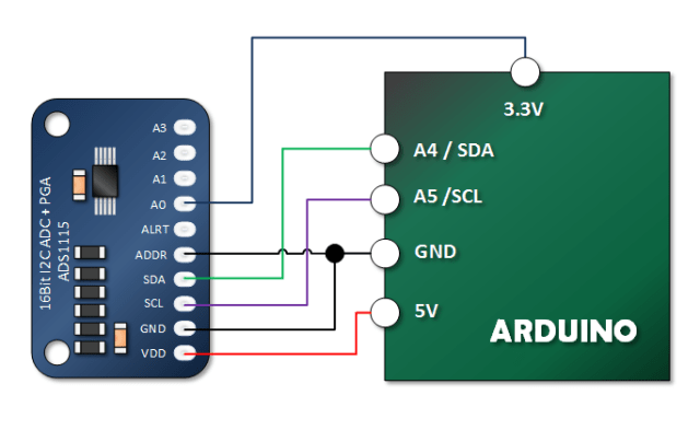
Connect the ADS1115 Module to Your Arduino
In this tutorial, we’re going to keep it real simple. We’re just going to measure the 3.3 volt pin on our Arduino.
Copy, Paste and Upload the ADS1115 Arduino Sketch
Notice the constructor where I insert the address 0x48. Notice how I also did not make any attempts to set the Programmable Gain Amplifier. This is because default value is already +/- 6.144 volts. In my loop, you will notice that I applied the 0.1875 mV scale factor related to this full scale range to my result.
#include <Wire.h>
#include <Adafruit_ADS1015.h>

Adafruit_ADS1115 ads(0x48);
float Voltage = 0.0;

void setup(void)
{
  Serial.begin(9600);
  ads.begin();
}

void loop(void)
{
  int16_t adc0;  // we read from the ADC, we have a sixteen bit integer as a result

  adc0 = ads.readADC_SingleEnded(0);
  Voltage = (adc0 * 0.1875)/1000; // Apply the scale factor (mV per bit) and convert to V

  Serial.print("AIN0: ");
  Serial.print(adc0);
  Serial.print("\tVoltage: ");
  Serial.println(Voltage, 7); // Print voltage with 7 decimal places
  Serial.println();

  delay(1000);
}
Verify Your Tutorial Output
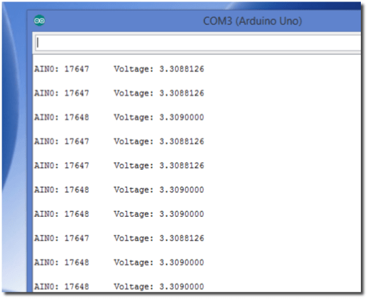
If you are successful, your output will look a lot like the picture below.
Notice how rock steady the result is. The difference between readings is less than one millivolt.
Now, what’s hard to determine is if that fluctuation is due to the 3.3 volt output from the Arduino, the ADS1115 or a combination of the two.
Never-the less, what we clearly have is a measurement that is very repeatable (precise). In fact, repeat-ability is often a lot more useful in measurements than accuracy. We can quantify the error in a very repeatable measurement and apply a little math to make it very accurate.
When the measurement is not very precise, we are stuck with a degree of uncertainty that is very difficult to correct for.