LTC2400 Arduino Voltmeter Module User Manual
A VERY Accurate Arduino Voltmeter
Using the analog inputs of the Arduino is one of the fundamental ways the micro-controller interfaces to sensors.
However in some cases, the 10 bit resolution of it’s analog measurements leaves something to be desired.
This little module makes it possible to boost the measurement precision to 24 bits. More, it includes the TI REF3040 voltage reference to not only make the measurements precise, but accurate as well.
Functional Description
The Linear Technology’s LTC2400 24 Bit Analog to Digital Converter (ADC) sits at the heart of the module.
Providing the precision reference voltage is the Texas Instrument REF3040.
Better precision can be achieved by removing an inductor and providing your own precision reference.
Communication with the Arduino is via it’s SPI interface.
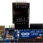
The design of the module is such that plugs directly into the UNO’s board headers.
The default measurement range is from 0 to 4.096. With an installation of a jumper, the measurement range is easily extended to 17 volts.
With minor modifications, you could extend this range to well beyond the 17 volts.
Basic Specifications
| Default Range | 0 to 4.096 Volts DC |
| Optional Range | 0 to 17 Volts DC |
| Supply Voltage | 5.0 VDC |
| Resolution | 24 Bits |
Arduino Voltmeter Module Pin Outs
The picture below provide a rear view of the module. It is followed by some key points about these pins.
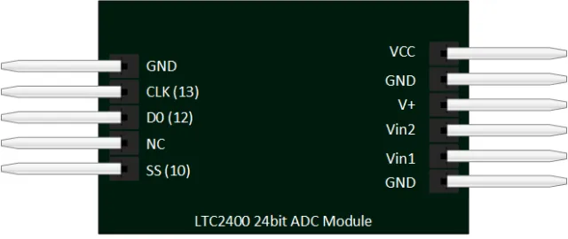
Left Side: Shows the connections to your Arduino UNO. It plugs nicely into your header. You will be using sketch that configures Arduino pins 10, 12, and 13 for a SPI interface.
VCC: is where you will connect your Arduino 5VDC output. This not only powers the LTC2400, but provides the voltage necessary to develop the precision reference from the REF3040.
GND: needs to be connected to the negative side of your voltage measurement. It is the same electrical point as the GND for your arduino. Make sure you do an excellent job of analyzing your circuit before make a connection.
V+: This is where you would connect your own voltage reference. You would have to remove L1 for this to work.
Vin2: has a range of 17 VDC. In order to use this, you will need to install a jumper at JP2. Keep in mind, that using this voltage divider will put 10K in parallel with the voltage you are reading.
Vin1: is the default voltage input and has a range of 4.096 VDC.
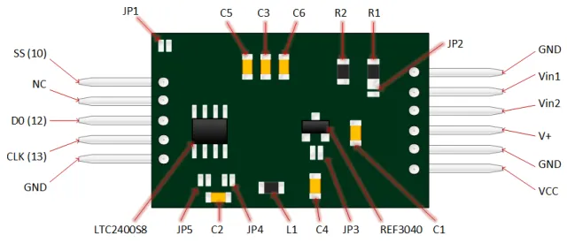
Component Side View
Below is an illustration showing the component side of the LTC2400 Arduino Voltmeter. Inductor L1 and jumper JP2 are shown.
Clicking on the picture will provide a larger view.